Anakin AOTC FX Conversion Tutorial
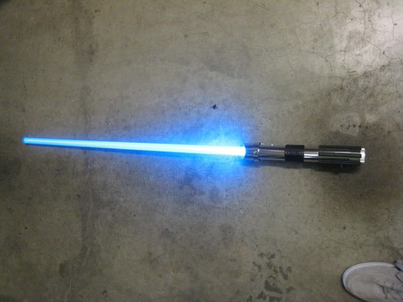
This tutorial will show you how to convert a 2002 Master Replicas Force FX Anakin Skywalker lightsaber. The saber will retain all light and sound functions, but have a removable blade and a high power luxeon LED as its light source.
This is an advanced conversion! Do not attempt if you are not very comfortable with soldering and drilling/tapping holes. It is the most complex saber to convert.
I am making this tutorial with the assumption that you know what you are doing when it comes to wiring a MR sound board and converting a saber. Read through the tutorial at least twice before starting the conversion.
Materials:
Anakin AOTC FX Saber
TCSS Mace Windu conversion kit
Rebel/P4/Luxeon LED
3x AA size dummy cells
1/4" long 8-32 set screw
3/8" long 10-32 button head screw
5mm accent LED (optional)
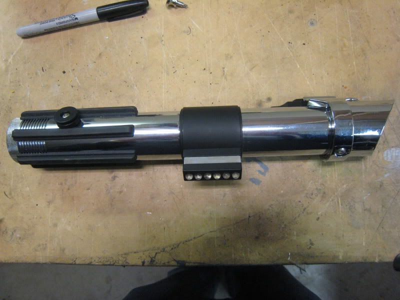
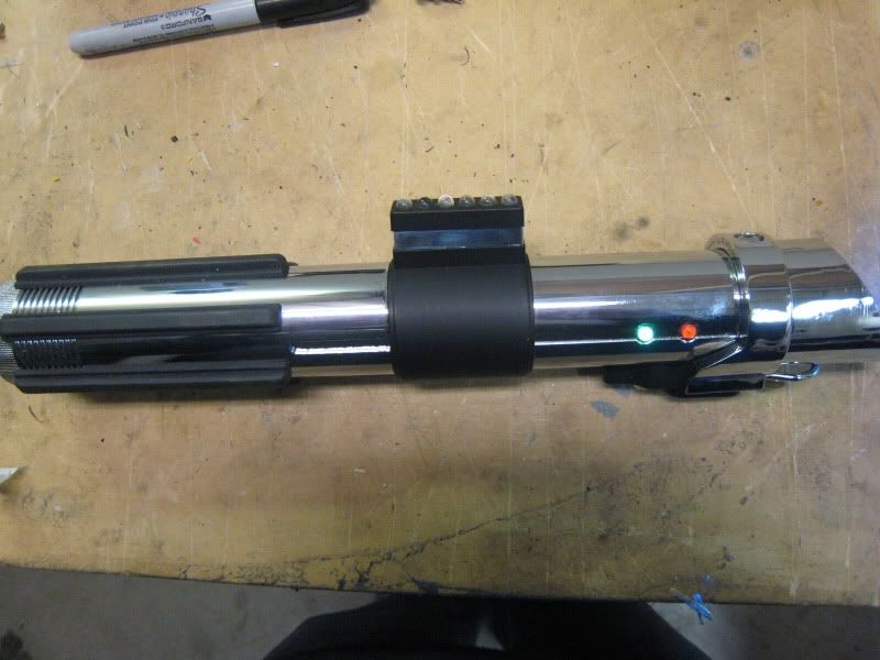
Pictures of stock MR Anakin:
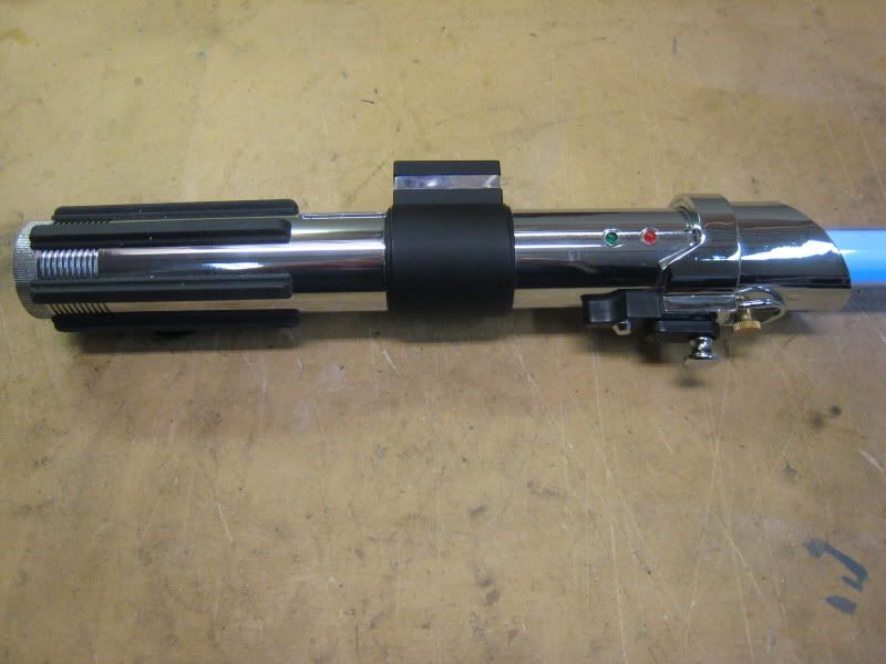
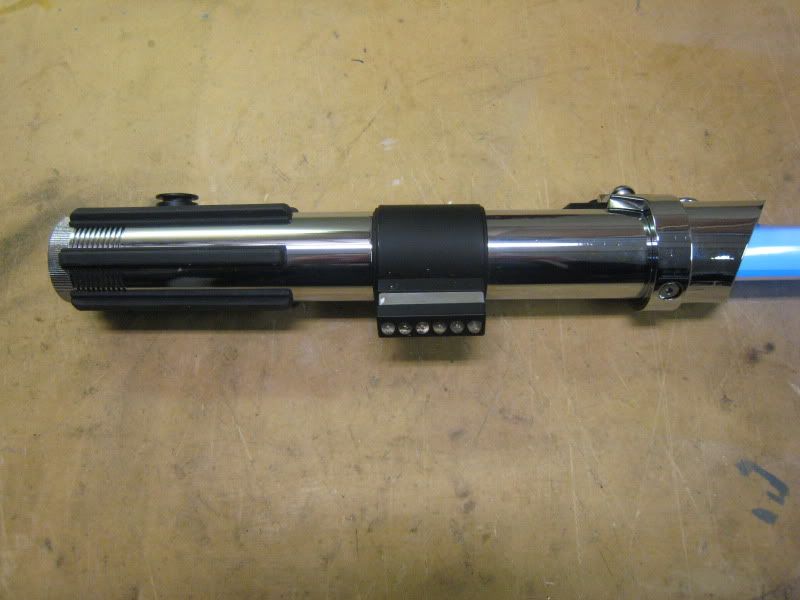
To start, take apart the control box. Remove both screws holding it on and remove the chromed plastic part. DO NOT remove the battery cover yet.
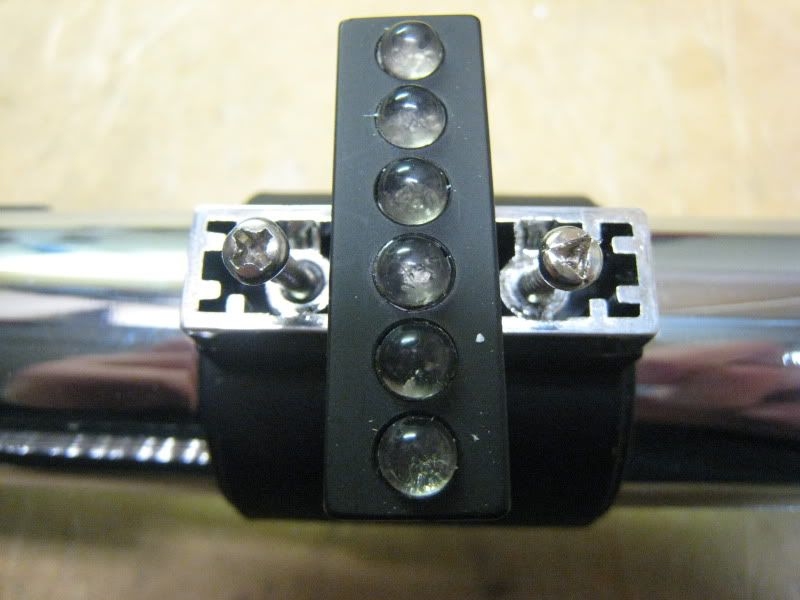
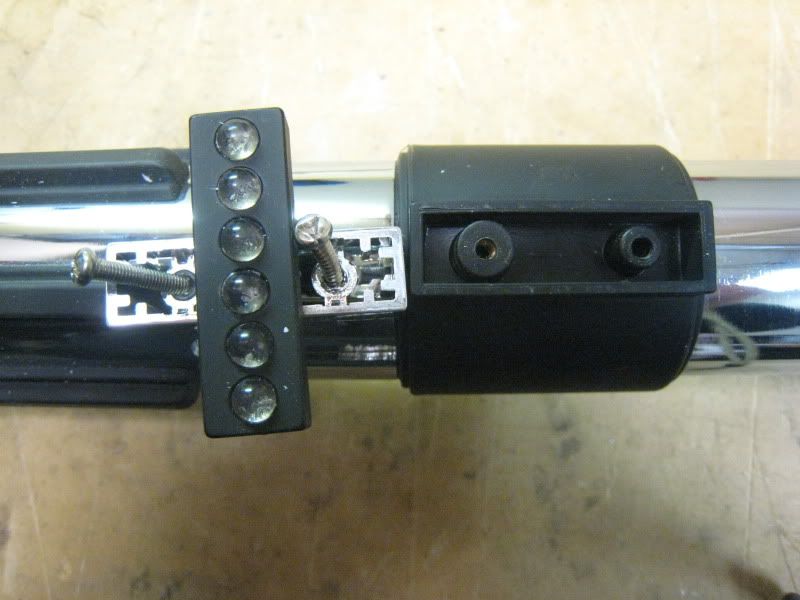
now is time to take apart the actual switch box. There are two chromed pieces that need to be removed. The one that fits fairly flush (left) needs to be pried off. Use an exacto knife and gently pry around till it pops off. The big one (right) unscrews.
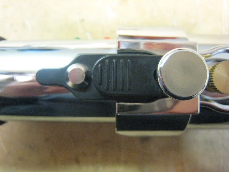
Now remove the last screw holding the box on. It is on the right in this picture.
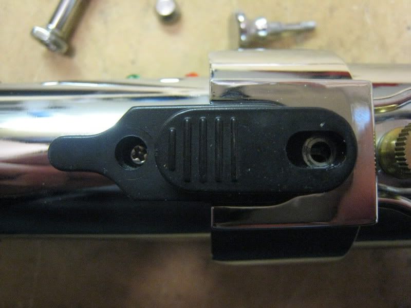
Pull the box off. Unplug the two quick disconnects and push them into the hilt so they sit flush.
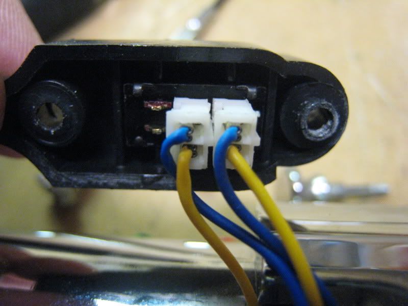
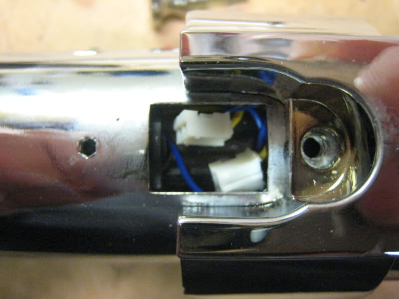
Remove the screw on the front of the emitter. It requires a 3mm Allen wrench. Pull the entire shroud piece off.
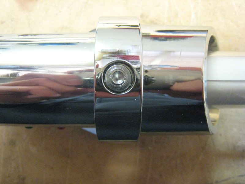
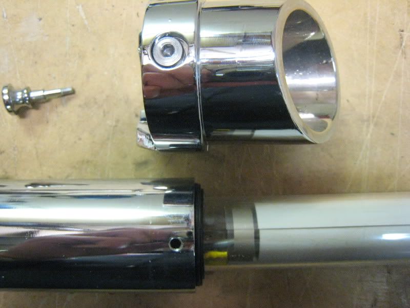
Now remove the bottom half of the saber.
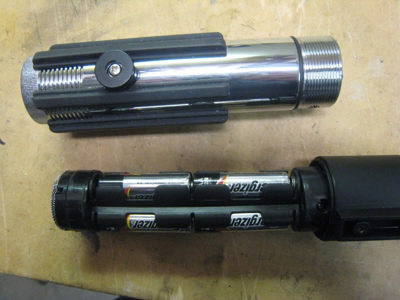
Push the electronics out through the bottom of the saber.
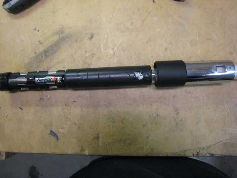
Remove all the screws holding the two plastic halves of the electronics together.
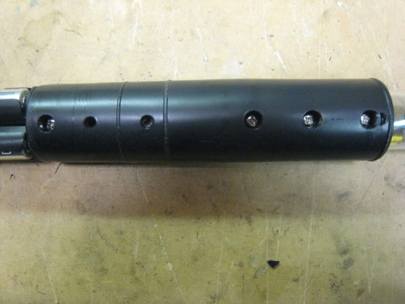
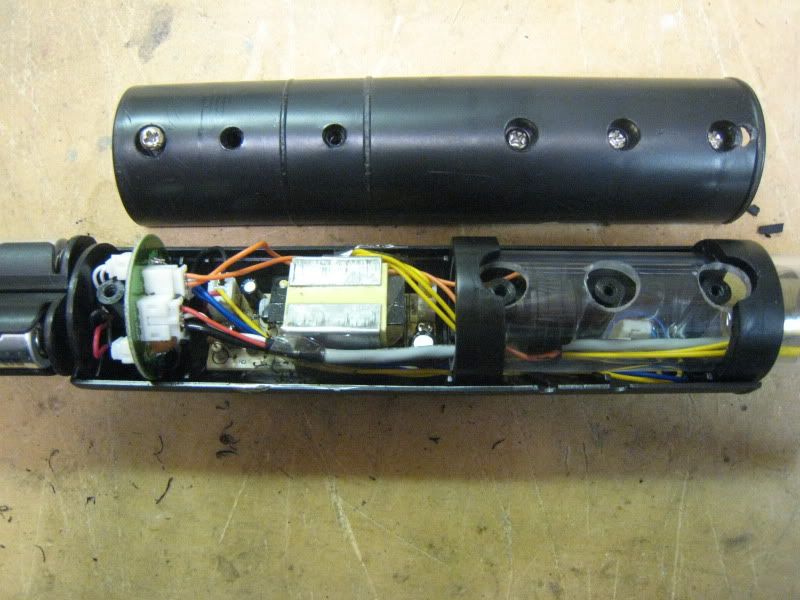
There are two small screws holding the EL inverter to the plastic housing. Remove them. They didn't photograph well, sorry. One is on each side of the big 'box' in the photo.
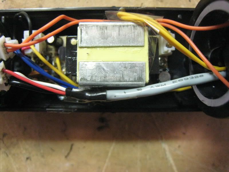
Pull all the electronics out. Get the wires spread apart like so. You will be doing some cutting next.
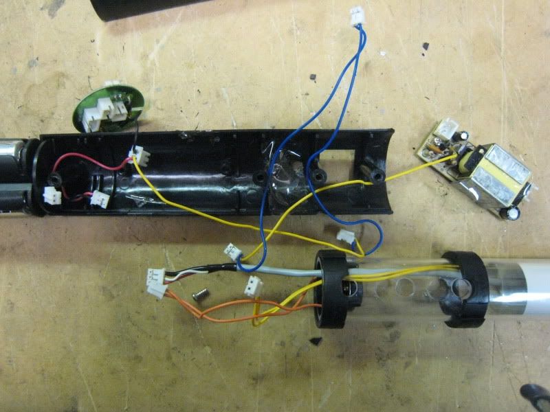
Cut the red wire from the 3-lead quick connect. This will free the circular PCB from the battery pack.
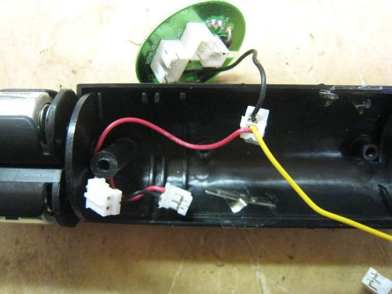
Cut all of the blue wire out of the connectors shown in this picture. You want to keep the long yellow lead attached to the quick connect. These are your switch leads.
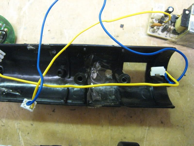
All done with cutting.
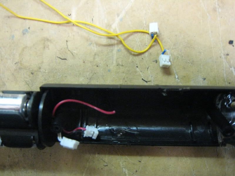
Here is the extra stuff you just cut out. You can discard it all.
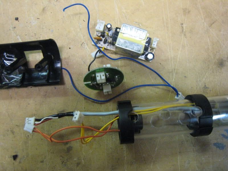
Time to wire up the new sound board. The board shown is from a 2005 Luke ROTJ. You need either this board or one from the 2005 Mace Windu. No other board will work!
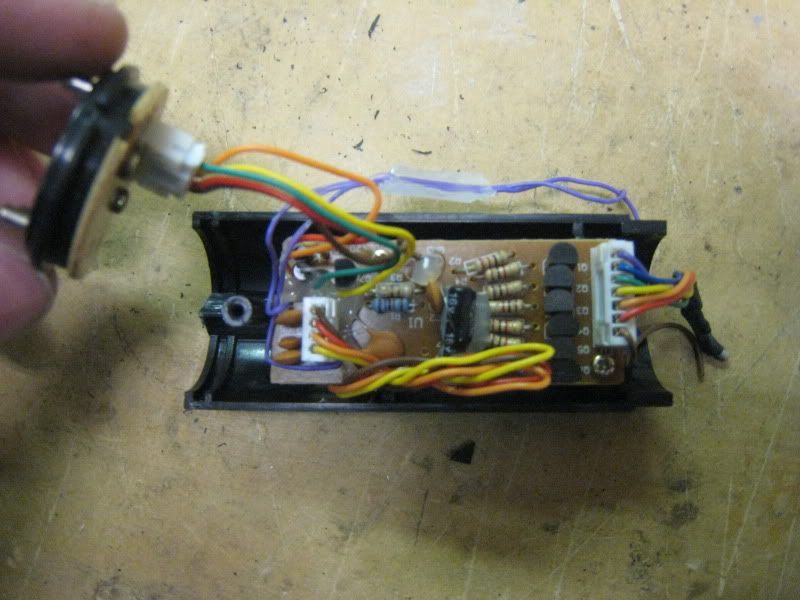
Remove the board from its sock housing. Remove all the hard glue from the wiring. Cut the wires off the quick disconnect that goes to the battery terminals.
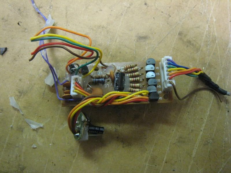
The two purple wires are your switch leads. Desolder them and solder on the yellow wires with quick connects on them (the ones you just cut off the stock setup).
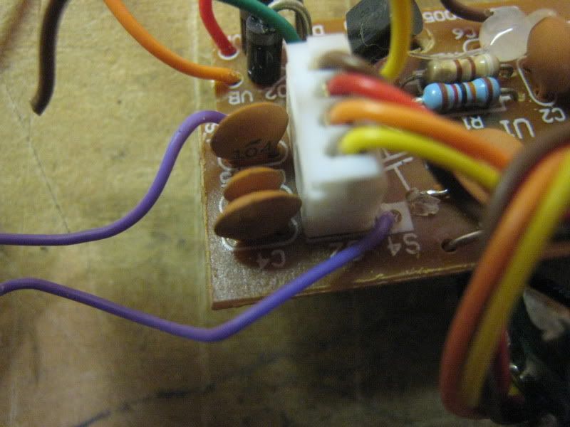
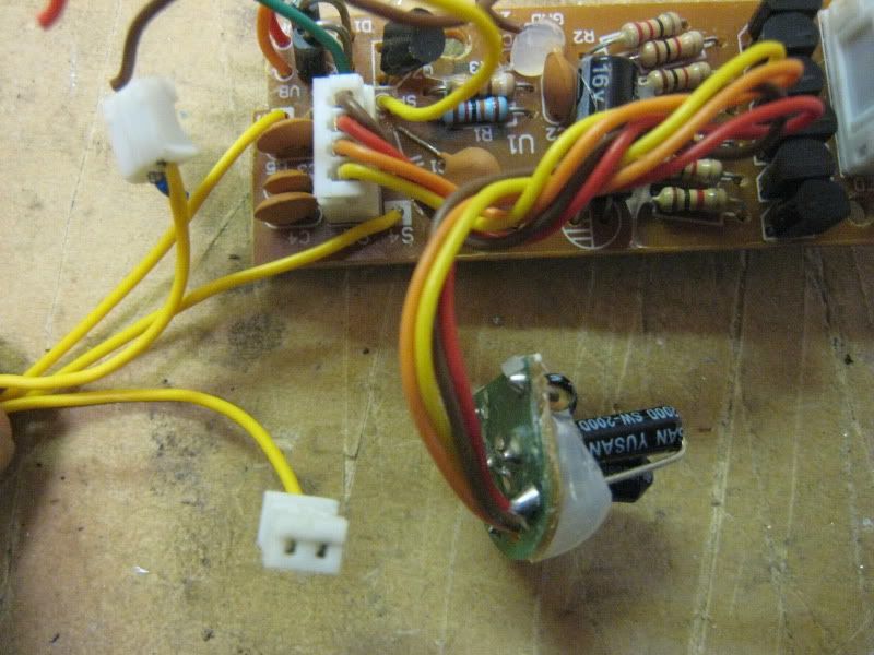
Time to give the sound board power. Remove the batteries from the battery pack. Cut off all the quick disconnects that are on the wires. Strip and tin all leads. You should have something like this.
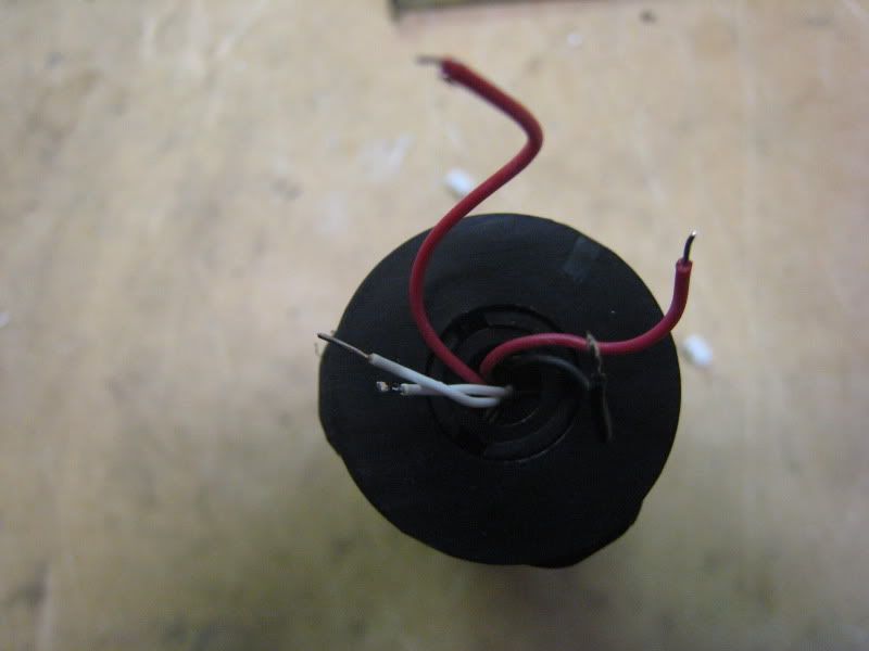
Strip and tin the five wires from the sound board that you cut a few steps ago (they were all on one QD).
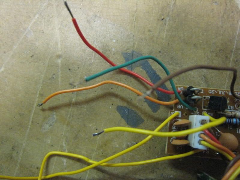
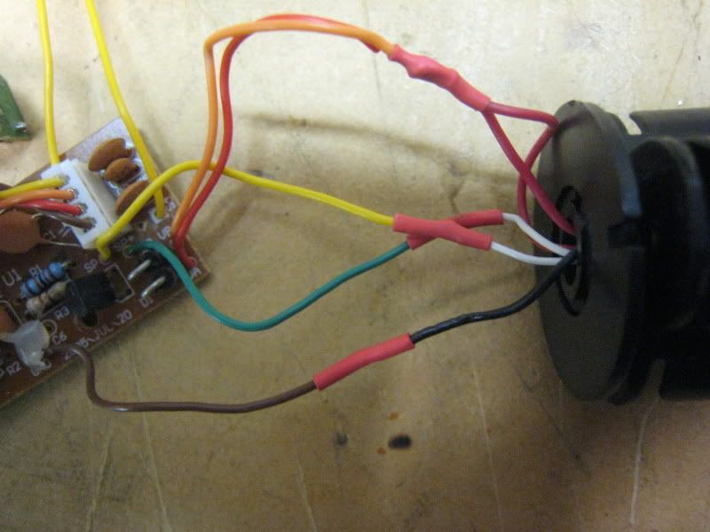
Time to wire everything together. Heatshrink is mandatory. Electrical tape is not a suitable substitute.
Board---------------Battery pack
Brown--------------Black
Green--------------White (either one)
Yellow-------------White (either one)
Red&Orange----Red (both leads)
Put your electronics aside now. It is time to cut the stock blade housing to accept the metal blade holder. Line them up just like normal and cut to length.
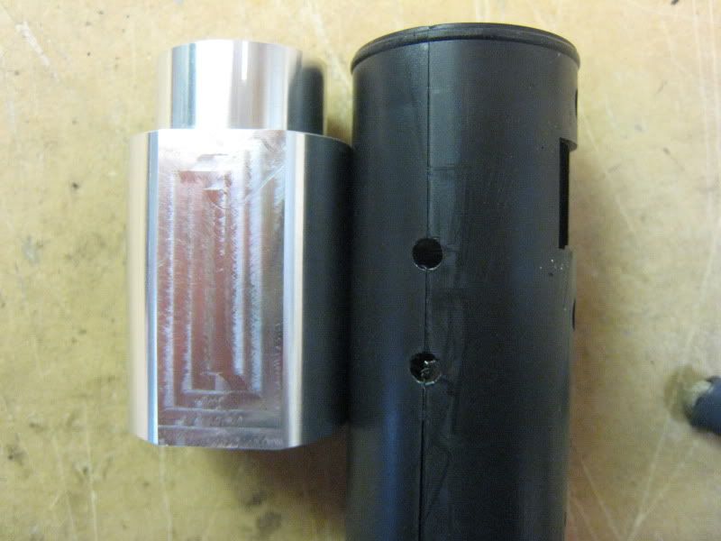
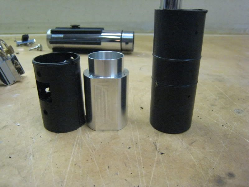
This is a trick part. To keep the blade holder from moving/spinning, you have to drill and tap a hole in the side of it. Line your blade holder up with the saber so one of the flat spots matches the hole for the switch box.
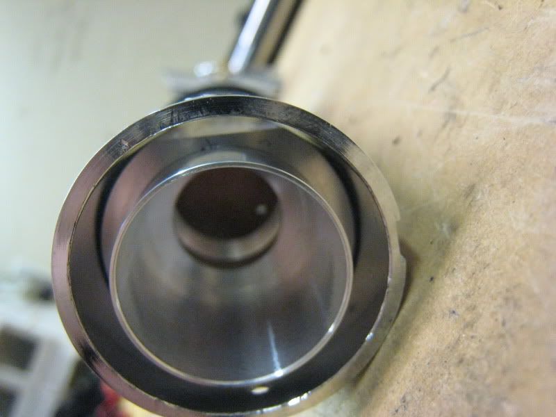
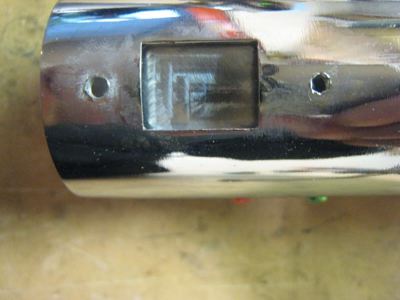
Drill and tap a hole to either side of the rectangular hole in the saber. Predrill to help stop the blade holder from rotating, then drill for an 8-32 screw. Tap the hole.
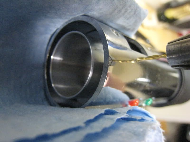
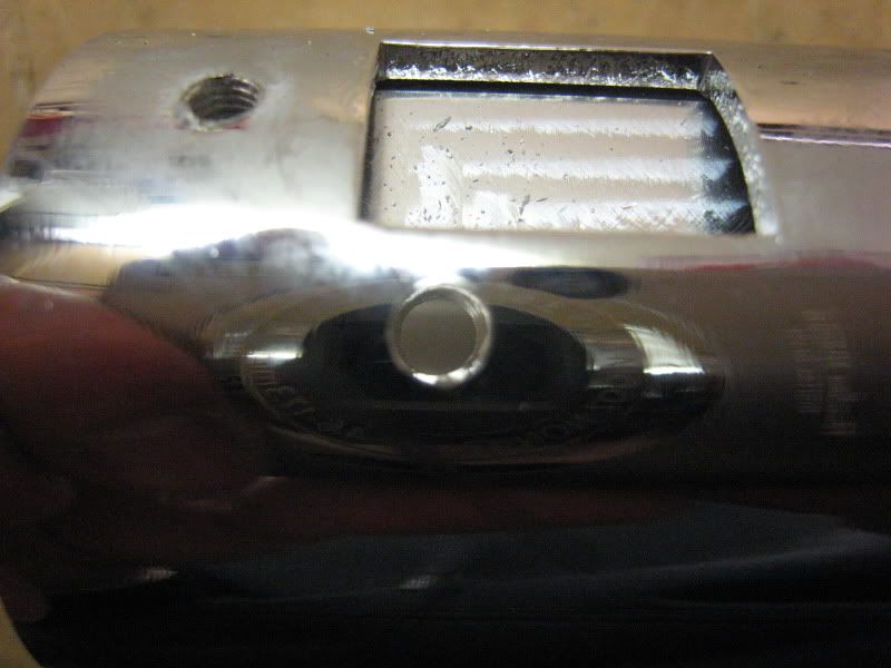
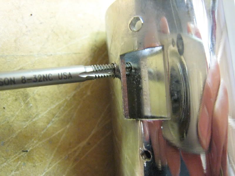
Install a 1/4" long, 8-32 screw. It will sit totally flush and not need to be sanded at all. The emitter shroud will cover it.
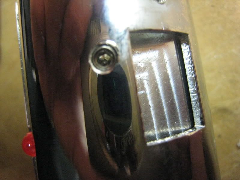
Here is an optional mod I thought I'd throw in. This will make the green and red fake LEDs light up. If you don't want this, ignore the next few steps. First, install your blade holder with the set screw in. Mark the line where the faux LEDs are.
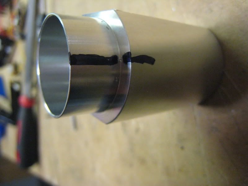
Take a hacksaw and cut a channel along the line you just drew. Don't go too deep, this picture shows about how far I went in.
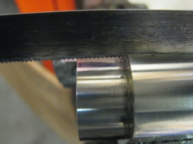
Now take a round file and file away. The channel you cut will help keep the file from sliding. I ended up filing considerably more than is pictured, almost down to the threads for the heatsink.
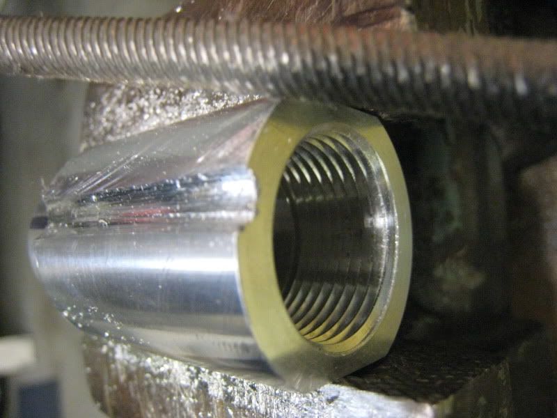
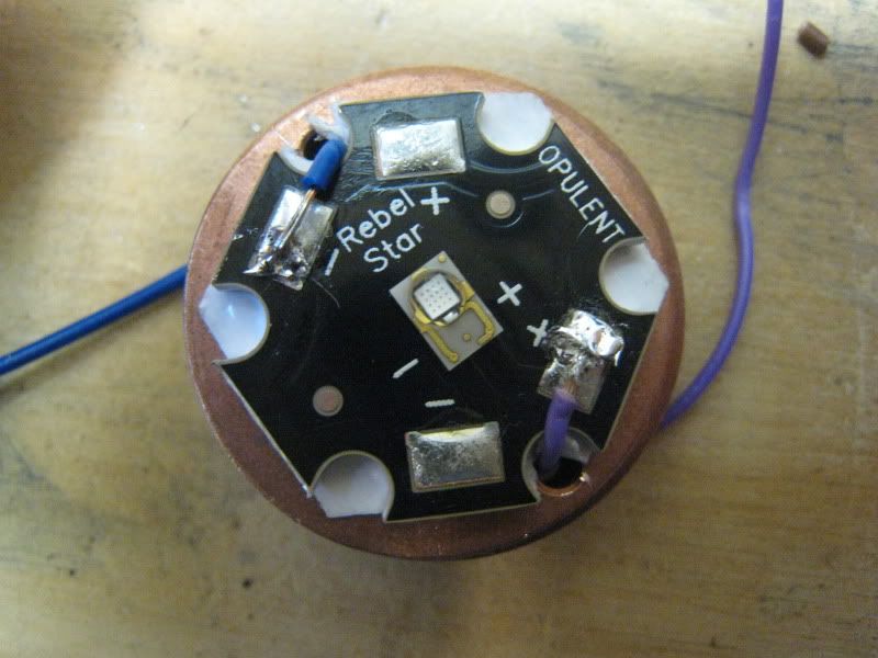
Wire up your LED. Thermal tape is a must. Install it in the conversion kit blade holder.
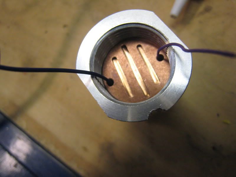
Now take the leads from the sound board. Strip and tin them all.
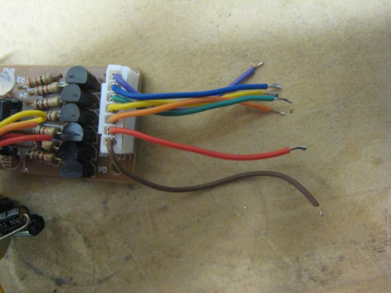
If you are doing the light-up accents mod, wire in the accent LED now. I went with a direct drive. Resist according to your LED. Blue from the board to the negative on the LED. Brown to the positive. Also wire the positive main LED lead to the brown lead. All other wires go to the negative on the main LED.
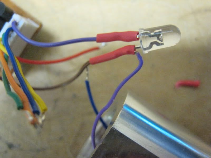
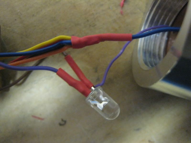
Now is a good time to test if you have it all wired up right. IMPORTANT: YOU MUST USE DUMMY CELLS IN THE BATTERY PACK OR YOU WILL FRY THE SOUND BOARD! Three dummies are needed. Put one in each 'column' of batteries. One of the actual batteries will heat up. Switch it with a dummy from another column. You should have one column that has two dummy cells in it.
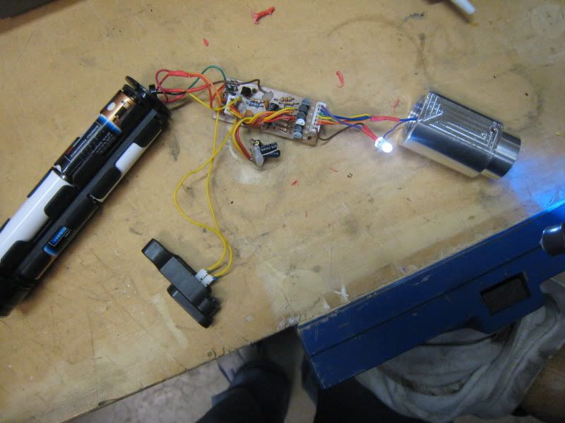
Put all the electronics into the plastic housing.
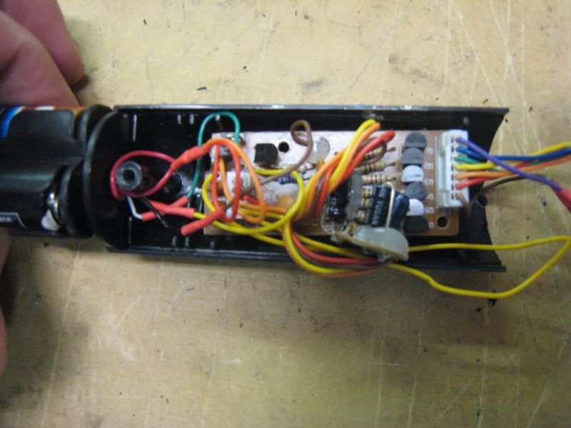
These next four pictures show alignment of the plastic housing with the blade holder. You need to cut two holes into the plastic housing. One for the accent LED and one for the switch leads.
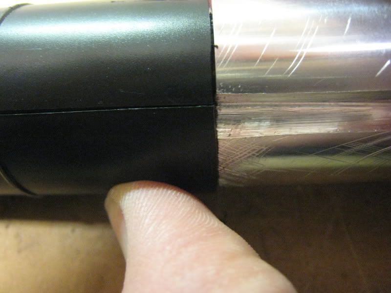
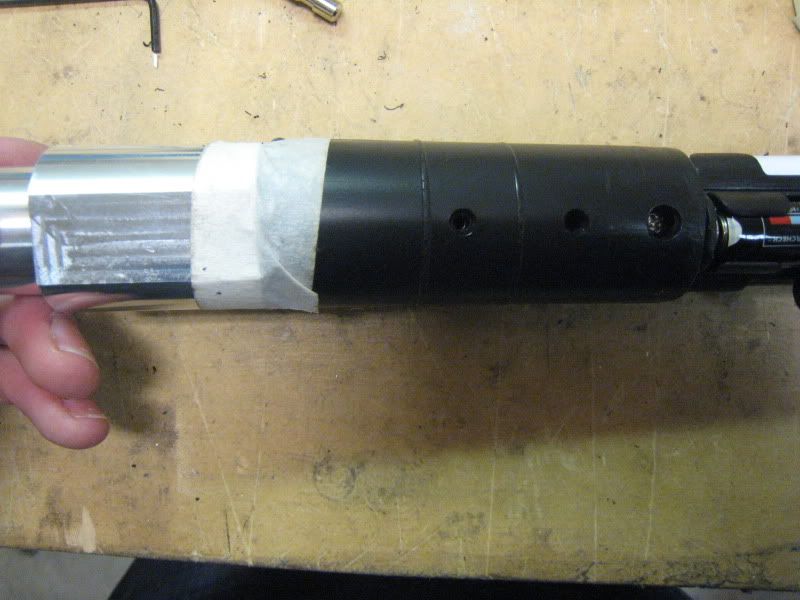
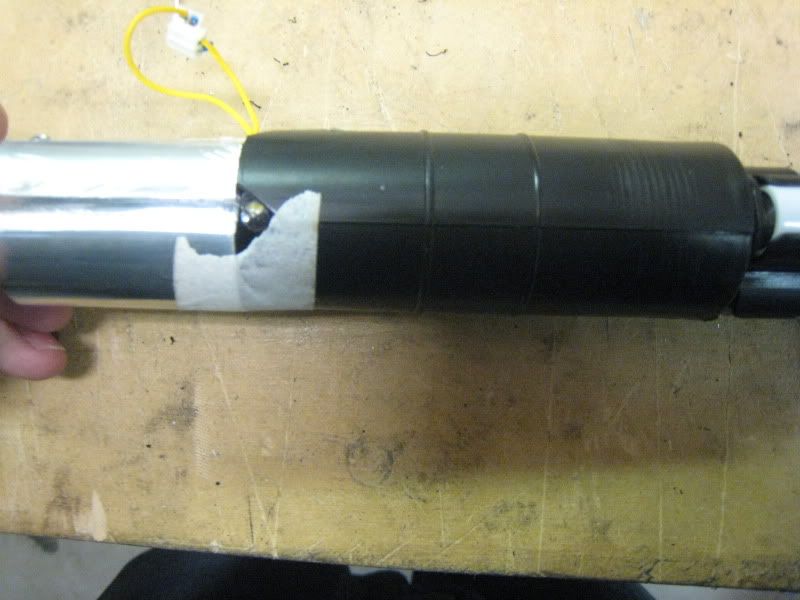
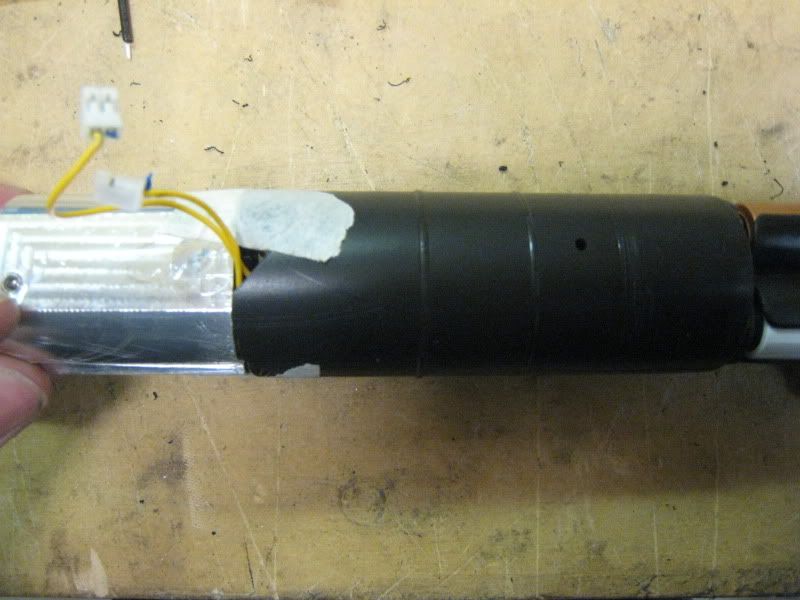
Cut the quick disconnects off your switch leads. Strip and tin the wires. Tape them down to the blade holder.
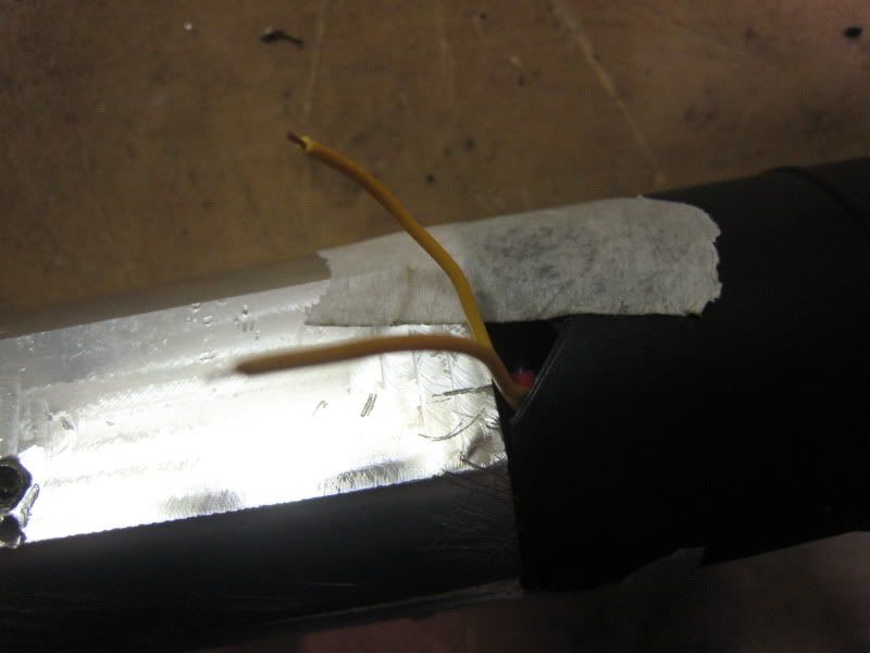
Push the electronics back into the hilt. Pull out the switch leads. Solder on the switch.
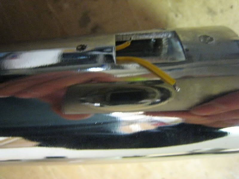
Reassemble the saber in reverse order, except for the two screws pictured.
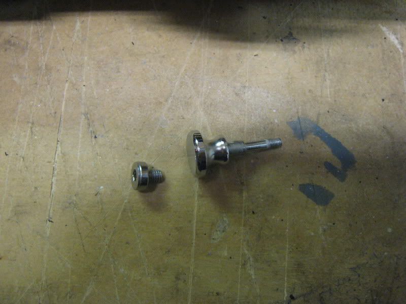
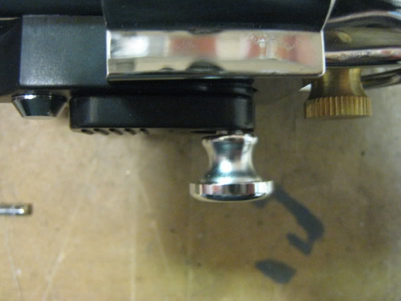
The big thumbscrew is too long to fit with the new blade holder. Cut it down and superglue it in. Be careful not to superglue the whole switch setup together.
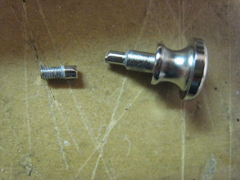
The flat screw will be replaced with a 10-32 thread, 3/8" long screw.
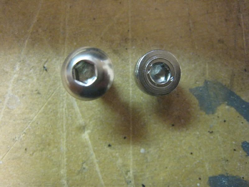
Drill and tap for the new screw, and install it. It won't need any sanding, 3/8" is the perfect length.
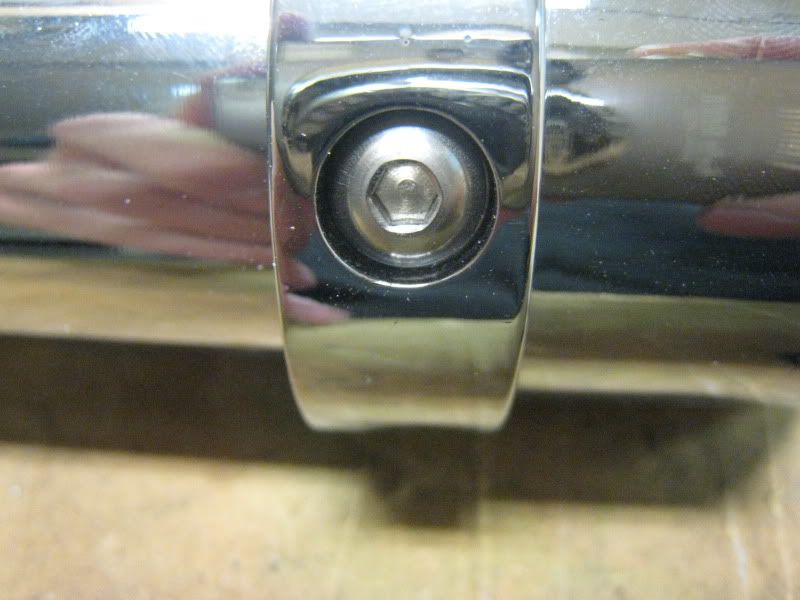
Congratulations, you've converted your saber!
