New Resource Apps added!
ISG has added some new Plecter Lab (Crystal Focus) help apps.
New LED.txt generator/player added!
New CF low battery/PLI threshold calculator added!
*New CF High Powered LED parameter calculator
These should help new and old users alike by letting them interactively build (and preview) their led.txt sequence animations, as well easily figure out the low batt. setting for their config file.............................. more to come.
Check them out!
http://www.holocronarchives.com/?page_id=77
Honing a Blade Holder Tutorial
This tutorial shows a simple way to hone out a blade holder. This is needed when using an Ultrasabers blade with a blade holder from TCSS.
Materials:
Drill Press (recommended) or hand drill
Shopvac
Eye, ear, and hand protection
Cylinder hone from McMaster-Carr
The hone you'll want to get is from http://www.mcmaster.com
When at the site, search for part number 4424A24
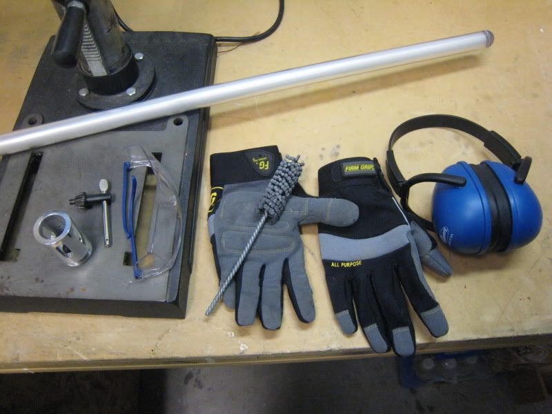
Quick shot of everything you need. The gloves were around $10 at Home Depot, I recommend getting something like them. The shopvac isn't pictured.
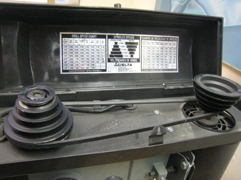
Make sure your drill press is on the lowest speed setting it has. Mine goes down to 640 rpm. Do not use a drill press if you can't make it spin below 1000 rpm.
Chuck the cylinder hone and then slide your blade holder onto it. Make sure that any screws are removed from the blade holder before honing.
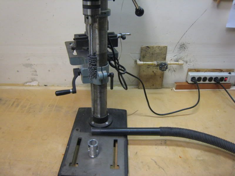
Now comes the tricky part. With one hand you will want to hold the blade holder and hose from the shopvac. The vacuum will suck in all the metal dust and keep the part cool while honing. This means you don't have to wash the part afterwords, and the part doesn't heat up while honing.
Turn the vacuum on, then the drill press. When honing, keep two hands on the blade holder at all times. Only remove a hand to turn the press on and off.
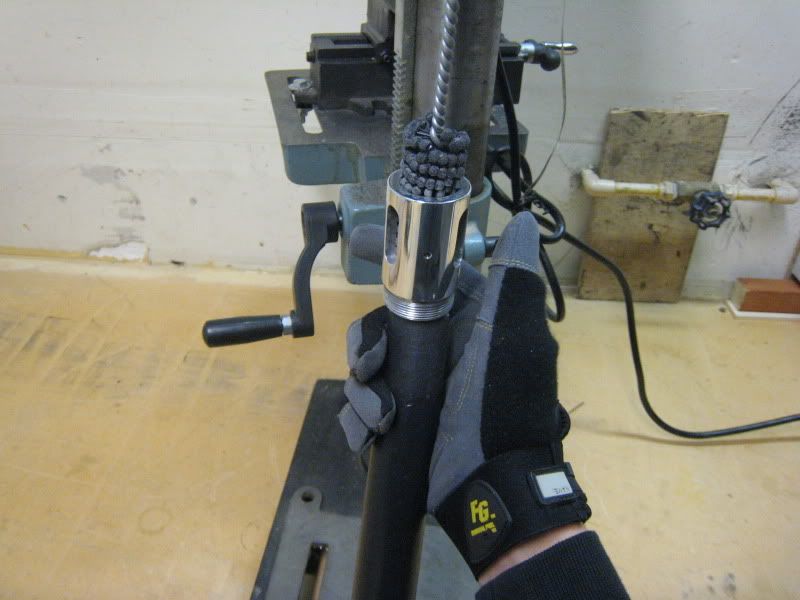
Check fitment every few minutes. Soon enough, your blade will fit perfectly.
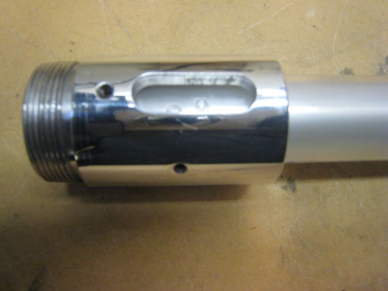
If you don't have a drill press available, this method can be used with a hand drill. Put the drill on the lowest speed setting. Have someone hold the drill and then you hold the part and vacuum. It's the same basic process.
Thread Tapping Tutorial
First off, the tools.
[color=Red][b]Required:[/b][/color] A thread tap (and the drill bit that comes with one). These come in many different thread pitches. Ultra uses 8-32 threading for his blade retention screws. If you strip out that screw, go to 10-32 thread pitch.
This is a picture of a tap and the drill bit it uses.
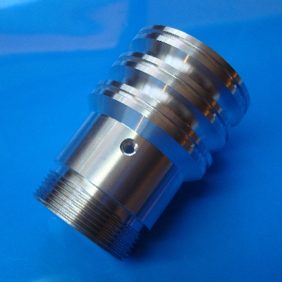
Some kind of power drill. A drill press is HIGHLY RECOMMENDED, because with hand drill, you risk the bit wandering.
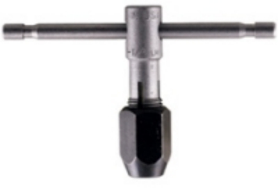
[color=Red][b]Optional, but HIGHLY recommended:[/b][/color] Tap handle. The tap handle holds the tap, like the chuck on a drill holds the bit. The handle allows you to keep the tap at 90 degrees, and gives you plenty of torque. You can tap without the handle, by using pliers to hold the tap. This isn't recommended though, and come on, the handle is all of 6 bucks. DO NOT USE A DRILL PRESS FOR THE TAPPING. YOU WILL DESTROY YOUR TAP.
[color=Red][b]The Idiot Proof Steps To Tapping[/b][/color]
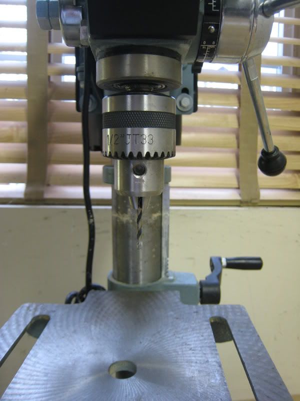
1) Secure the drill bit that comes into your drill. A drill press is HIGHLY recommended.
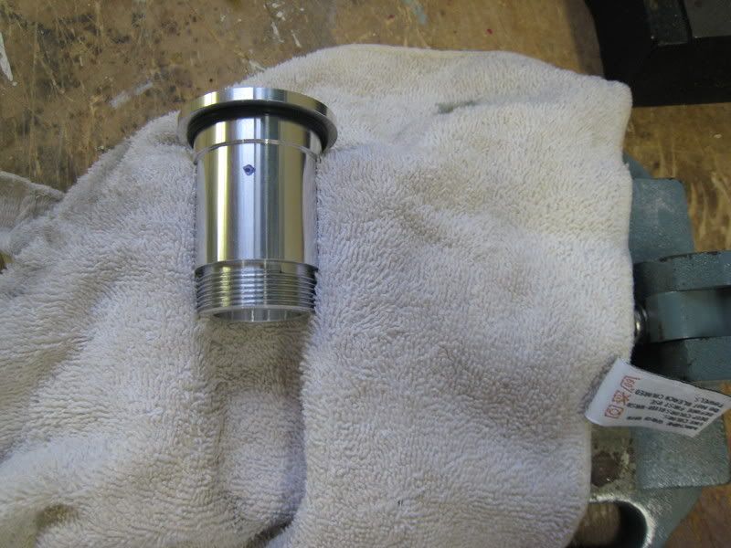
2) Secure the work piece. A drill press vice is HIGHLY recommended.
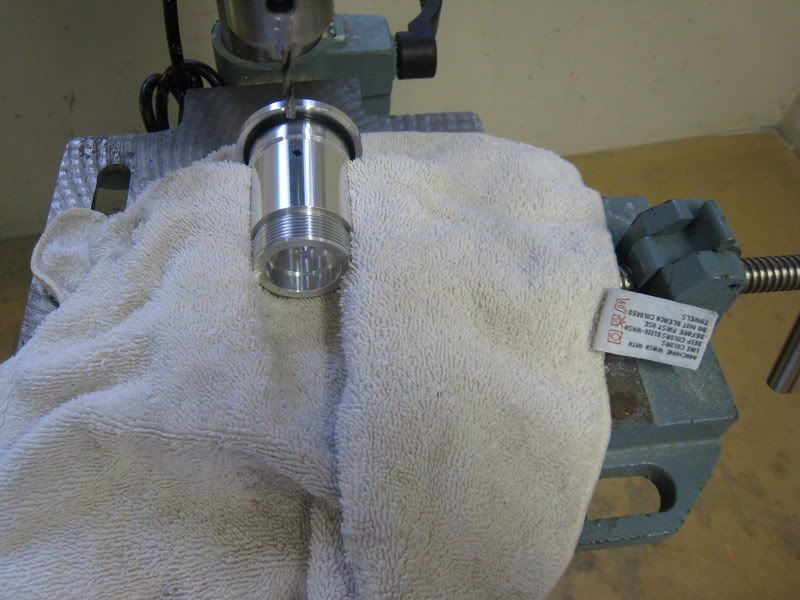
3) Drill the hole. Make sure you drill at the peak of the hilt's curve, otherwise, you will have a crooked hole.
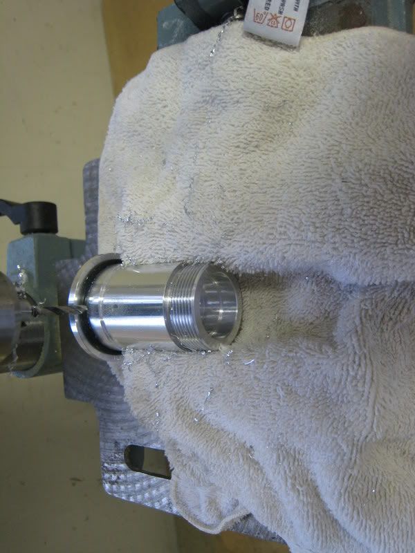
4) Clean out the hole, make sure that no metal scraps are still in the hole.
5) Attach the tap to tap handle. DO NOT USE DRILL PRESS INSTEAD OF A TAP HANDLE. YOU WILL DESTROY YOUR TAP AND HOLE.
6) Begin tapping the hole. You want to turn the tap handle 1/4 to 1/2 a rotation, and then back it out to remove material. Using lubrication during this step is highly recommended. DO NOT just tap the entire hole without backing out the tap. You run the risk of breaking that tap, and even if you don't, you will have a very poorly threaded hole.
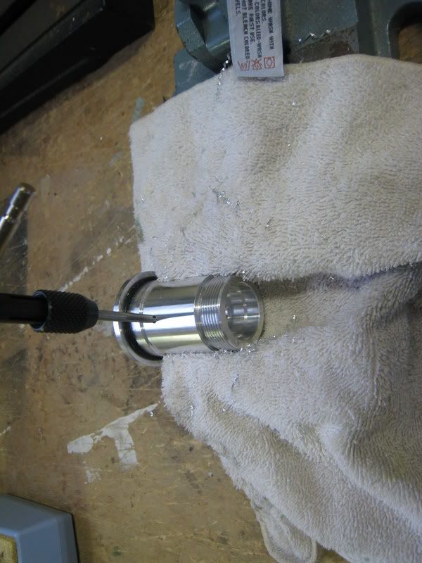
7) Run the tap through the hole one last time, just to make sure it is threaded well. Clean out any metal shavings still in the hole. A can of compressed air works well here.
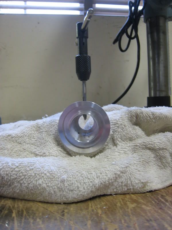
8 ) Thread your screw into the hole. Make sure you have the same thread pitch screw as hole. Otherwise, it won't work.
9) Enjoy your beautifully threaded hole ![]()
Here is a good drill bit-tap reference chart.
8-32 is M4x0.7.
6-32 is M3.5 x .06.
10-32 (I'm assuming that's "UNF") is M5 x .08.
4-40 is M3 x .05.
Here is a complete chart. Credit goes to Wikipedia.

Another formula is: to find the right size drill bit for the tap subtract the thread pitch from the screw size. Example: M5 screw with a .7 thread pitch would require a 4.3 drill bit.
Anakin AOTC FX Conversion Tutorial
This tutorial will show you how to convert a 2002 Master Replicas Force FX Anakin Skywalker lightsaber. The saber will retain all light and sound functions, but have a removable blade and a high power luxeon LED as its light source.
This is an advanced conversion! Do not attempt if you are not very comfortable with soldering and drilling/tapping holes. It is the most complex saber to convert.
I am making this tutorial with the assumption that you know what you are doing when it comes to wiring a MR sound board and converting a saber. Read through the tutorial at least twice before starting the conversion.
Materials:
Anakin AOTC FX Saber
TCSS Mace Windu conversion kit
Rebel/P4/Luxeon LED
3x AA size dummy cells
1/4" long 8-32 set screw
3/8" long 10-32 button head screw
5mm accent LED (optional)
Pictures of stock MR Anakin:
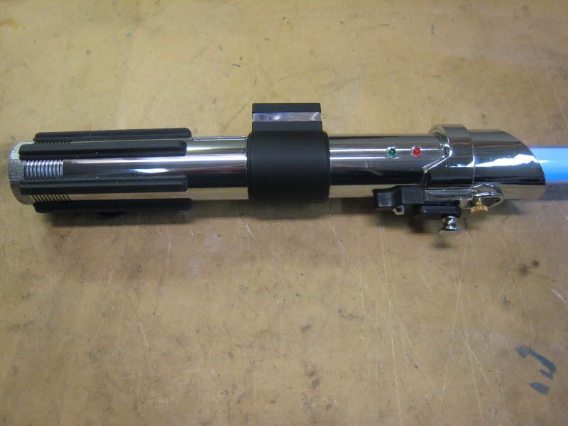
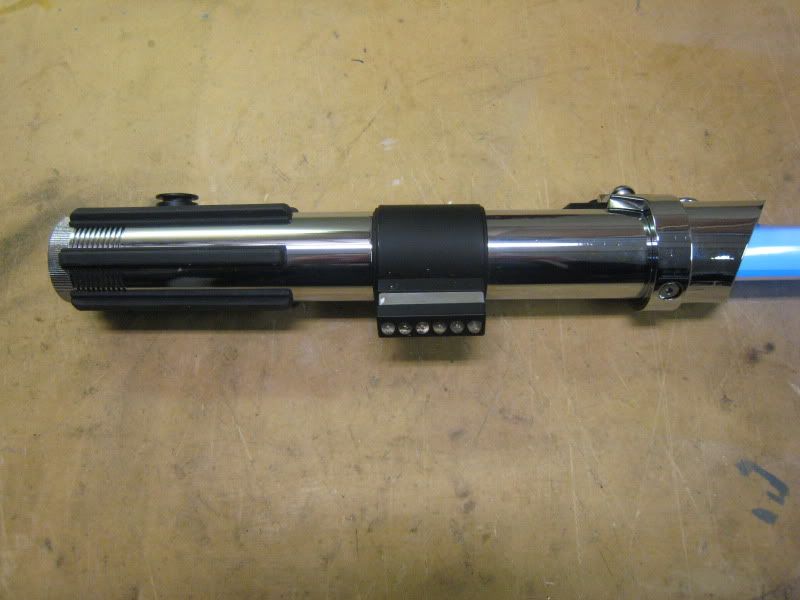
To start, take apart the control box. Remove both screws holding it on and remove the chromed plastic part. DO NOT remove the battery cover yet.
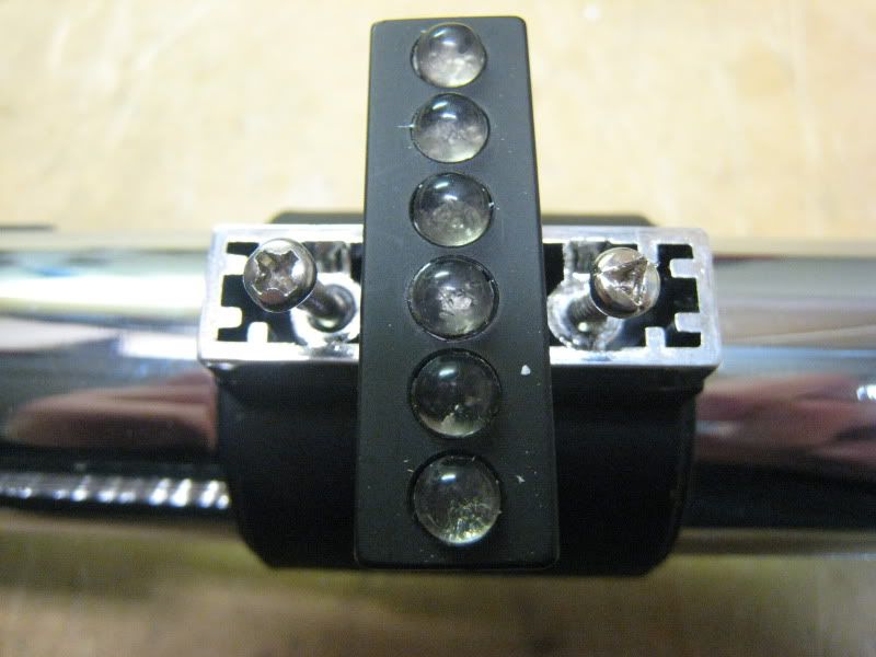
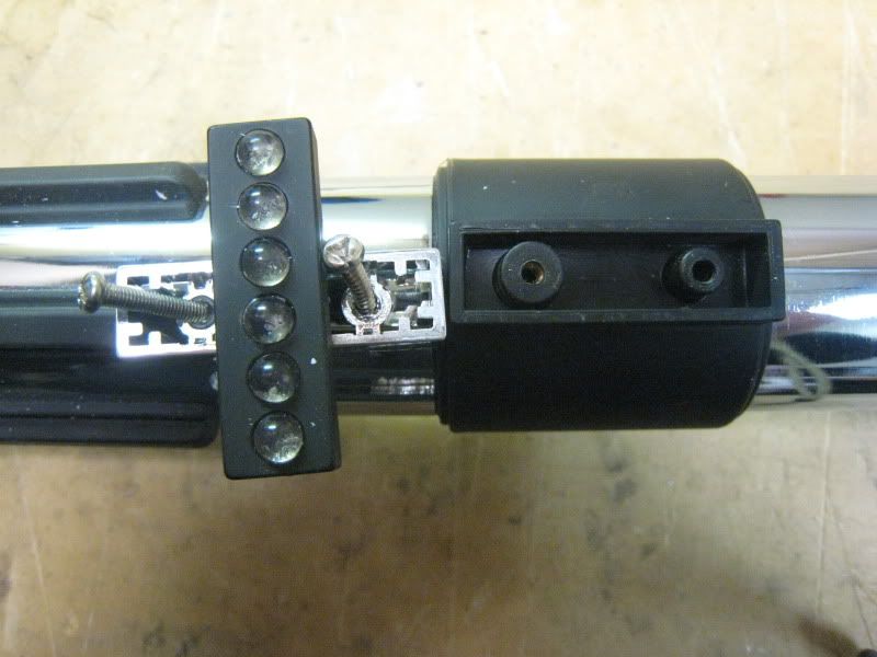
now is time to take apart the actual switch box. There are two chromed pieces that need to be removed. The one that fits fairly flush (left) needs to be pried off. Use an exacto knife and gently pry around till it pops off. The big one (right) unscrews.
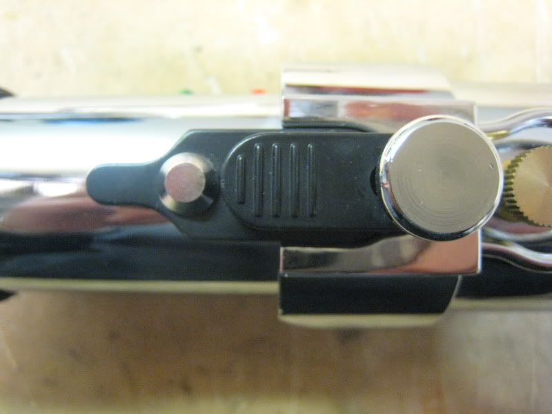
Now remove the last screw holding the box on. It is on the right in this picture.
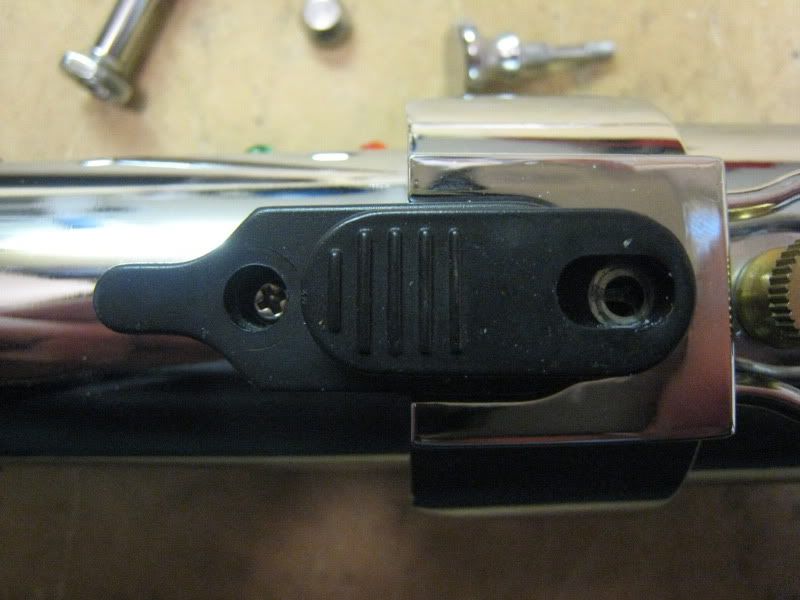
Pull the box off. Unplug the two quick disconnects and push them into the hilt so they sit flush.
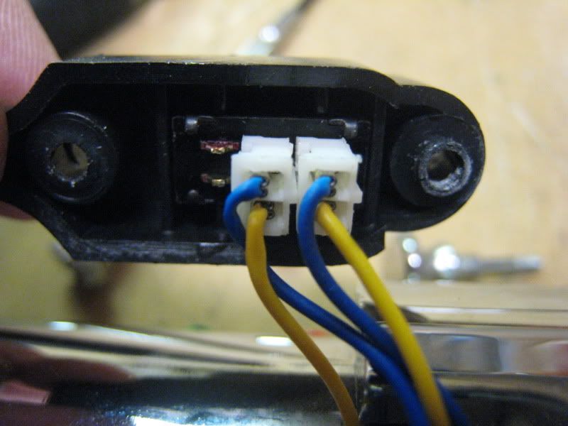
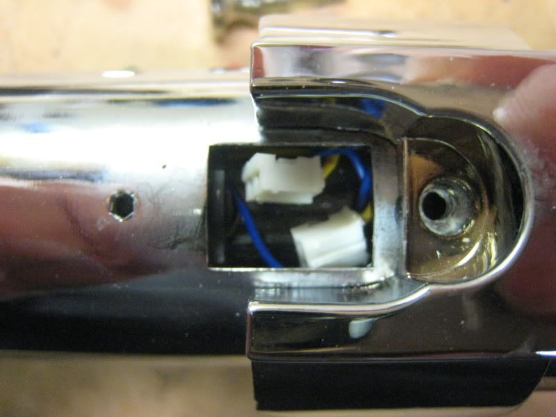
Remove the screw on the front of the emitter. It requires a 3mm Allen wrench. Pull the entire shroud piece off.
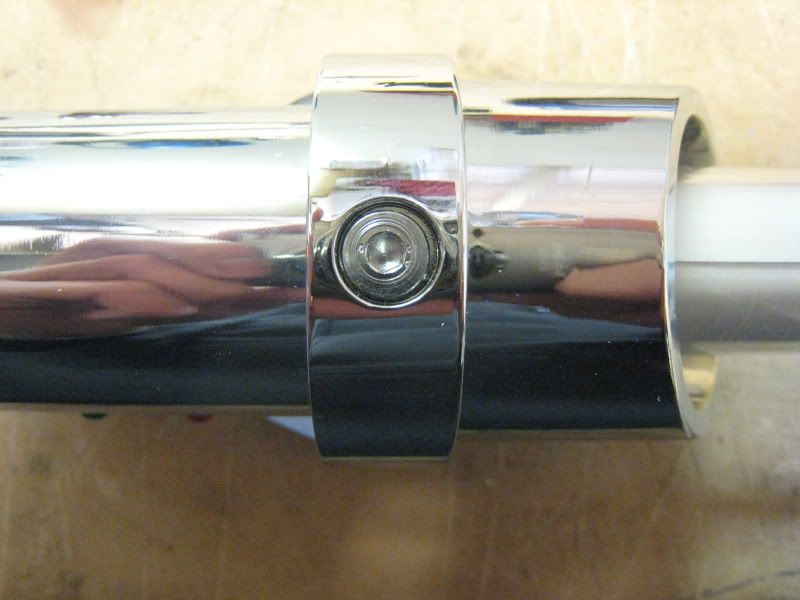
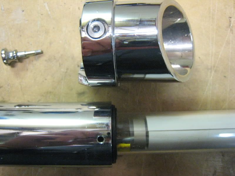
Now remove the bottom half of the saber.
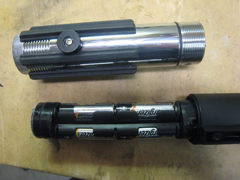
Push the electronics out through the bottom of the saber.
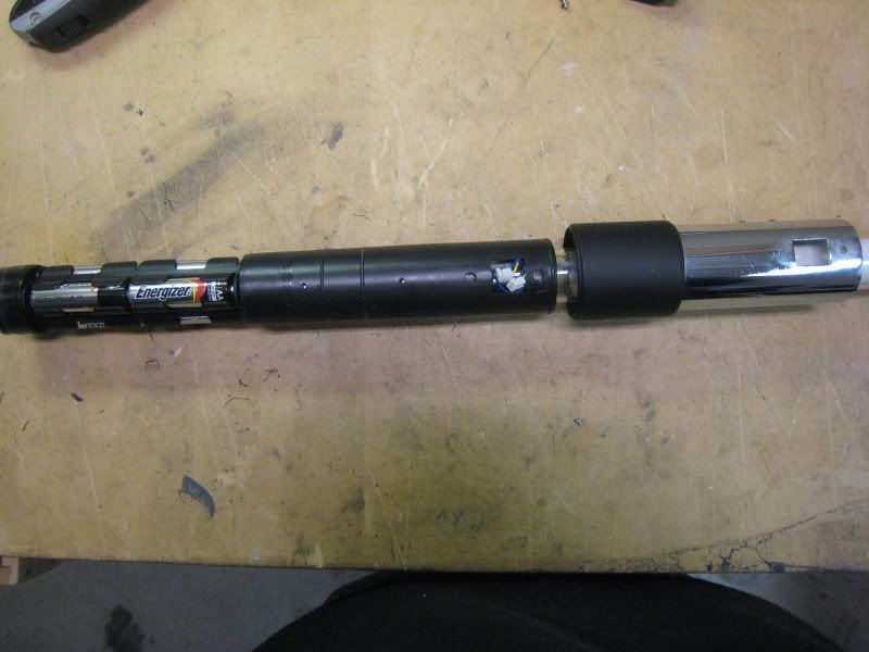
Remove all the screws holding the two plastic halves of the electronics together.
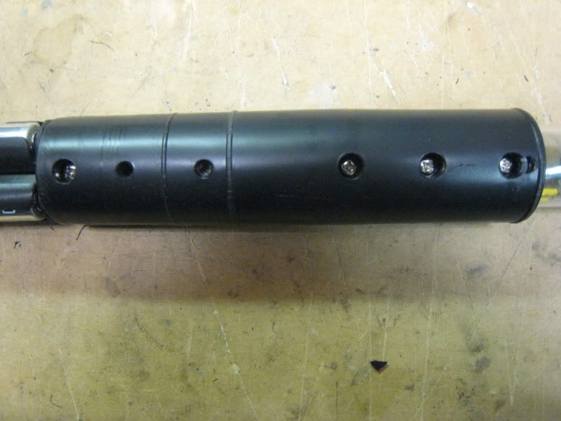
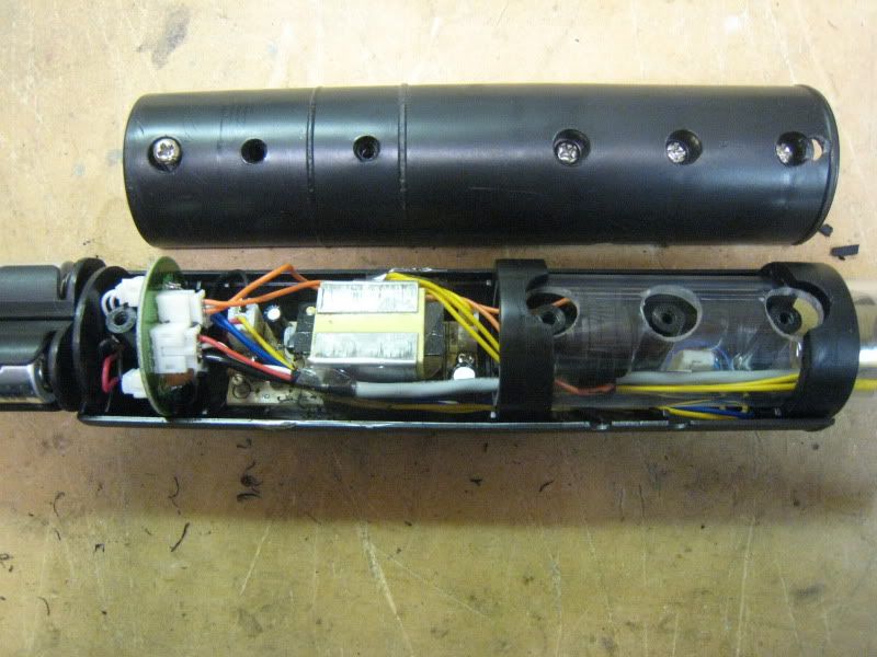
There are two small screws holding the EL inverter to the plastic housing. Remove them. They didn't photograph well, sorry. One is on each side of the big 'box' in the photo.
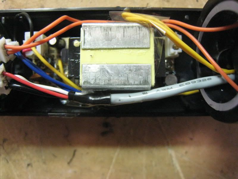
Pull all the electronics out. Get the wires spread apart like so. You will be doing some cutting next.
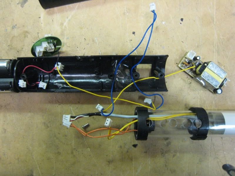
Cut the red wire from the 3-lead quick connect. This will free the circular PCB from the battery pack.
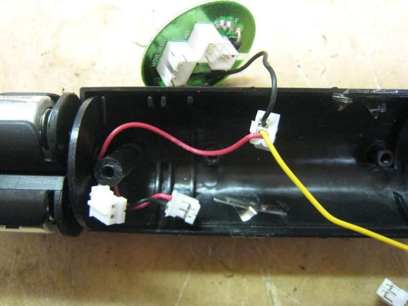
Cut all of the blue wire out of the connectors shown in this picture. You want to keep the long yellow lead attached to the quick connect. These are your switch leads.
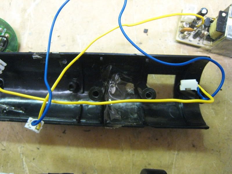
All done with cutting.
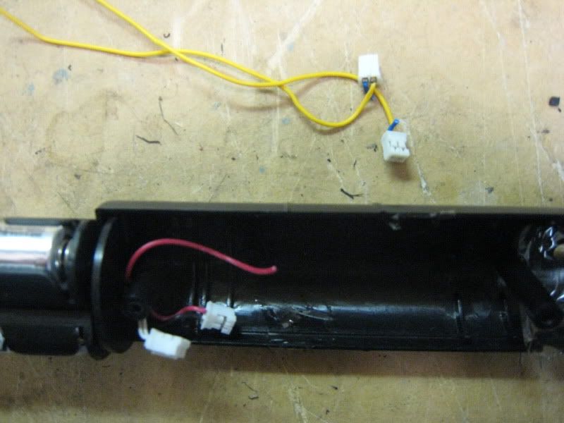
Here is the extra stuff you just cut out. You can discard it all.
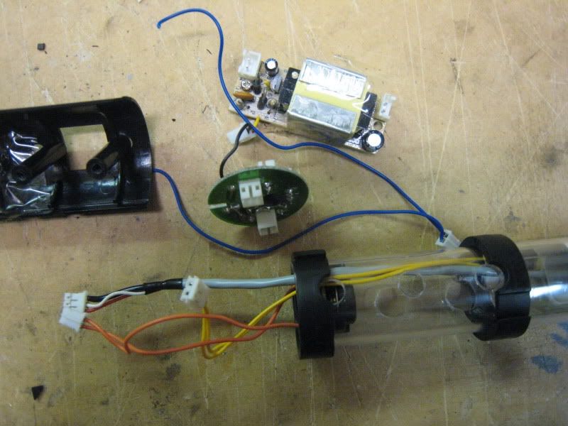
Time to wire up the new sound board. The board shown is from a 2005 Luke ROTJ. You need either this board or one from the 2005 Mace Windu. No other board will work!
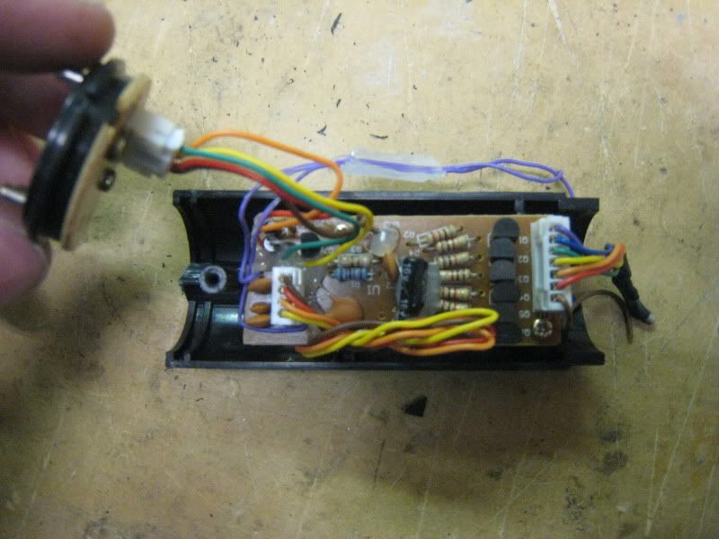
Remove the board from its sock housing. Remove all the hard glue from the wiring. Cut the wires off the quick disconnect that goes to the battery terminals.
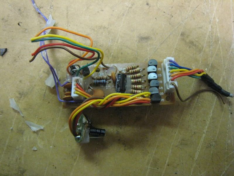
The two purple wires are your switch leads. Desolder them and solder on the yellow wires with quick connects on them (the ones you just cut off the stock setup).
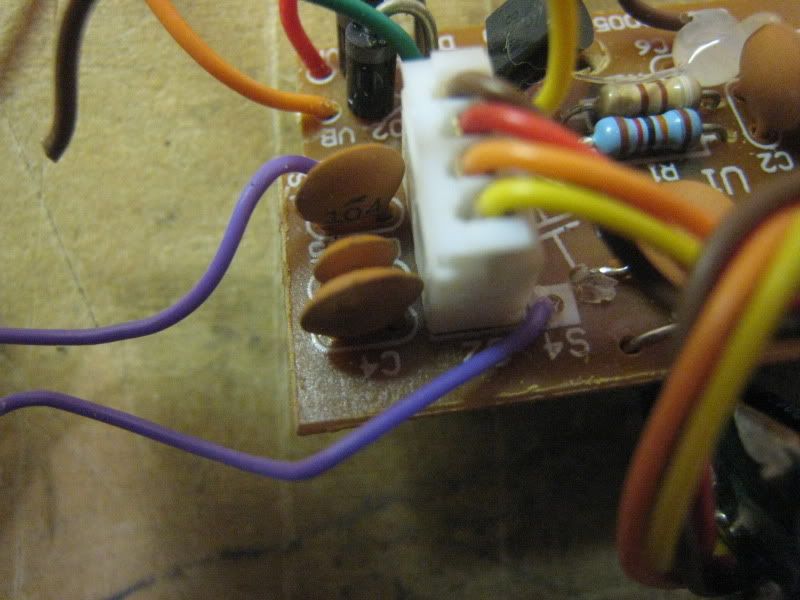
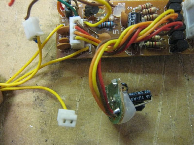
Time to give the sound board power. Remove the batteries from the battery pack. Cut off all the quick disconnects that are on the wires. Strip and tin all leads. You should have something like this.
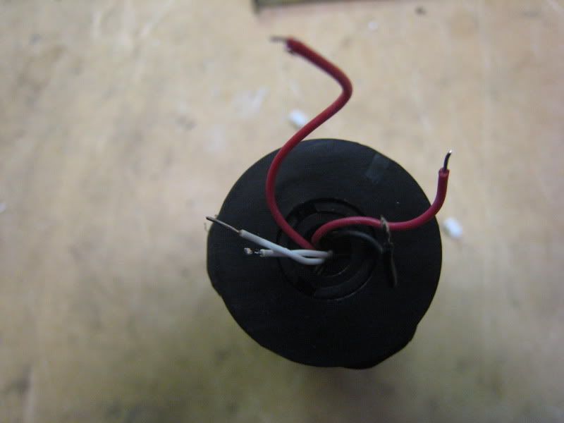
Strip and tin the five wires from the sound board that you cut a few steps ago (they were all on one QD).
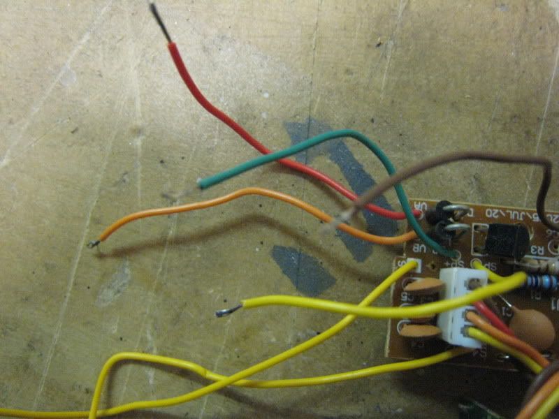
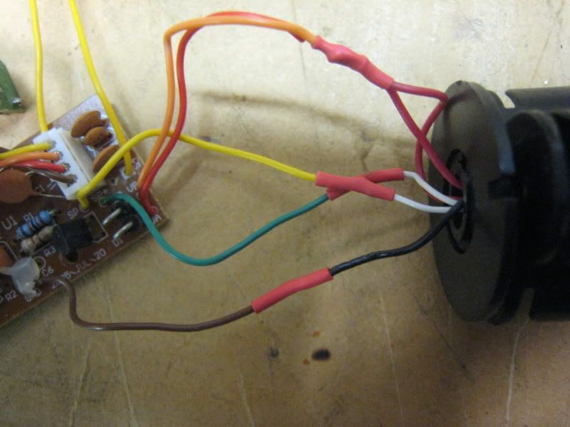
Time to wire everything together. Heatshrink is mandatory. Electrical tape is not a suitable substitute.
Board---------------Battery pack
Brown--------------Black
Green--------------White (either one)
Yellow-------------White (either one)
Red&Orange----Red (both leads)
Put your electronics aside now. It is time to cut the stock blade housing to accept the metal blade holder. Line them up just like normal and cut to length.
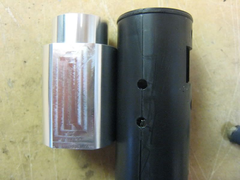
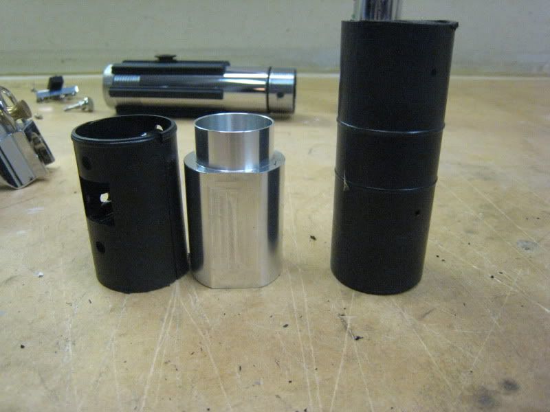
This is a trick part. To keep the blade holder from moving/spinning, you have to drill and tap a hole in the side of it. Line your blade holder up with the saber so one of the flat spots matches the hole for the switch box.
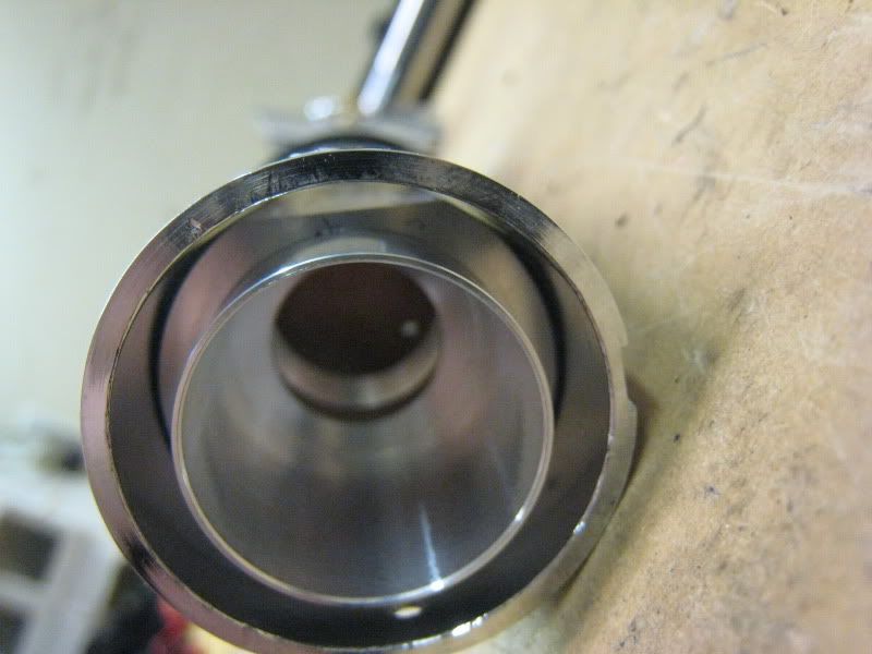
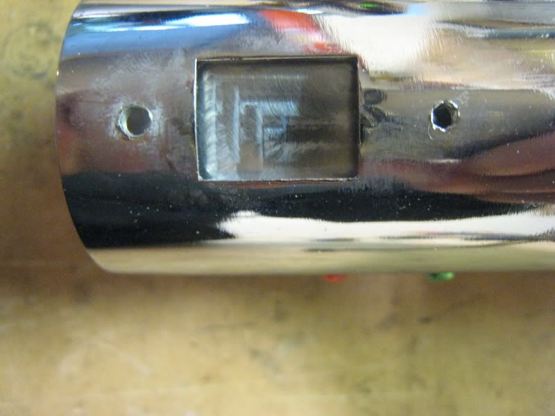
Drill and tap a hole to either side of the rectangular hole in the saber. Predrill to help stop the blade holder from rotating, then drill for an 8-32 screw. Tap the hole.
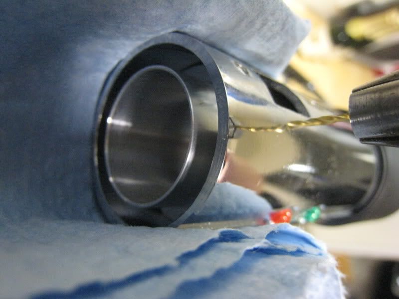
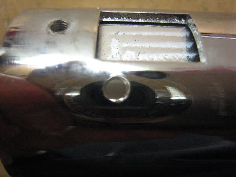
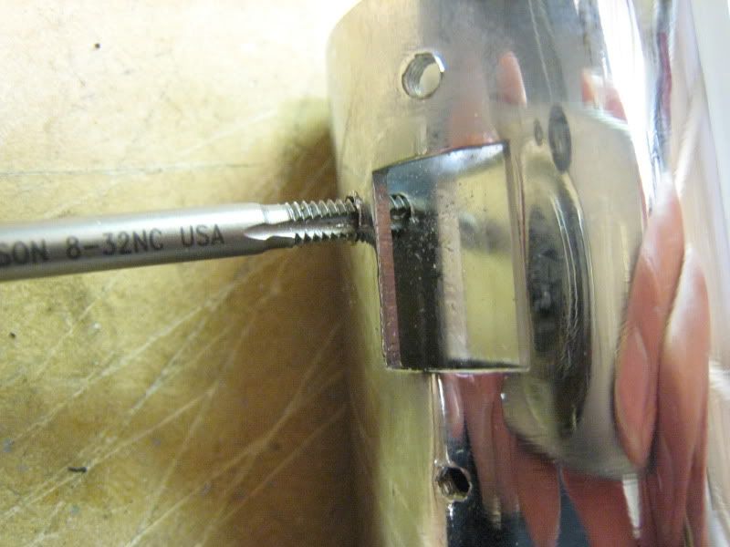
Install a 1/4" long, 8-32 screw. It will sit totally flush and not need to be sanded at all. The emitter shroud will cover it.
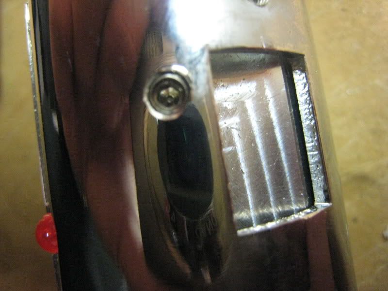
Here is an optional mod I thought I'd throw in. This will make the green and red fake LEDs light up. If you don't want this, ignore the next few steps. First, install your blade holder with the set screw in. Mark the line where the faux LEDs are.
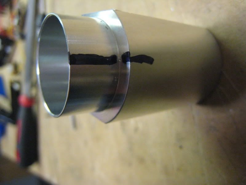
Take a hacksaw and cut a channel along the line you just drew. Don't go too deep, this picture shows about how far I went in.
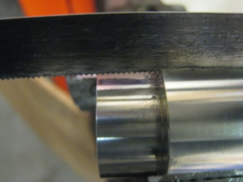
Now take a round file and file away. The channel you cut will help keep the file from sliding. I ended up filing considerably more than is pictured, almost down to the threads for the heatsink.
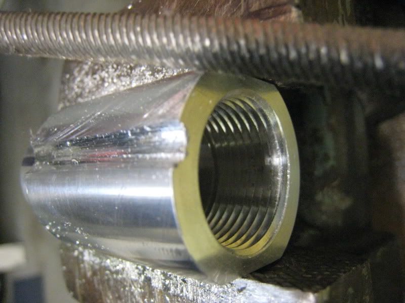
Wire up your LED. Thermal tape is a must. Install it in the conversion kit blade holder.
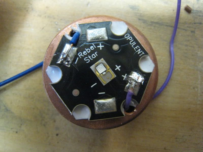
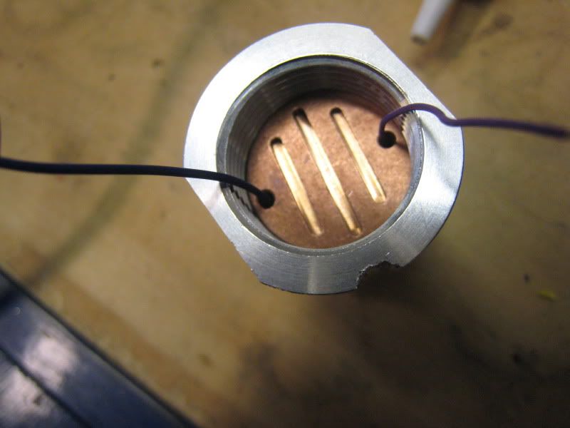
Now take the leads from the sound board. Strip and tin them all.
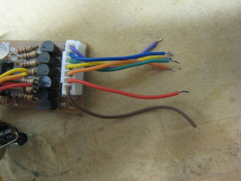
If you are doing the light-up accents mod, wire in the accent LED now. I went with a direct drive. Resist according to your LED. Blue from the board to the negative on the LED. Brown to the positive. Also wire the positive main LED lead to the brown lead. All other wires go to the negative on the main LED.
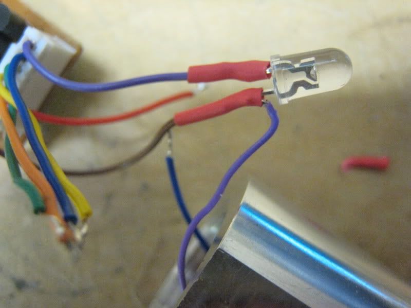
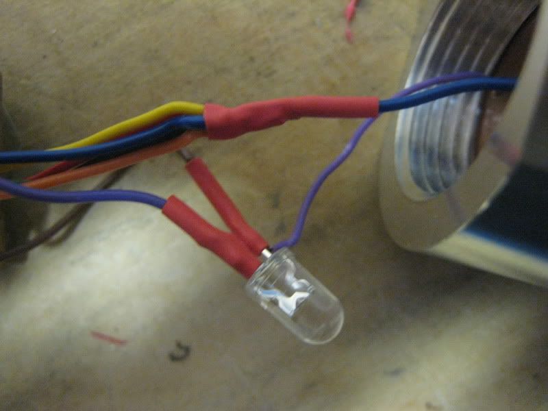
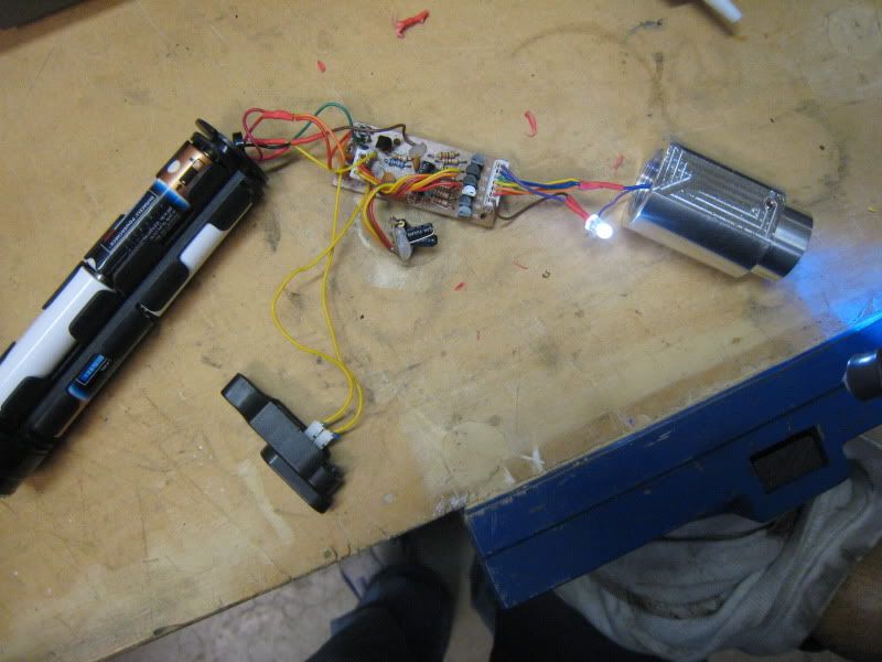
Now is a good time to test if you have it all wired up right. IMPORTANT: YOU MUST USE DUMMY CELLS IN THE BATTERY PACK OR YOU WILL FRY THE SOUND BOARD! Three dummies are needed. Put one in each 'column' of batteries. One of the actual batteries will heat up. Switch it with a dummy from another column. You should have one column that has two dummy cells in it.
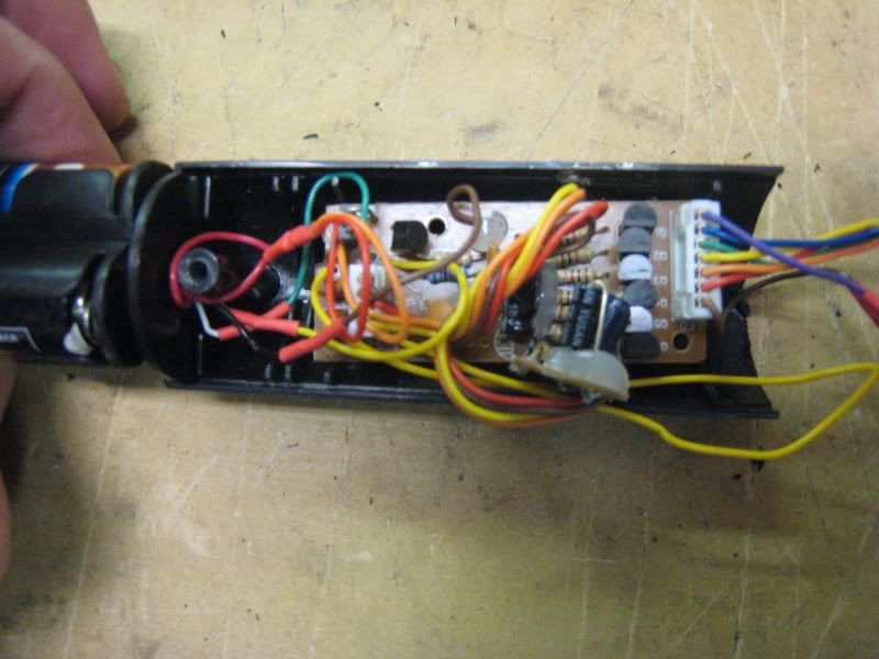
Put all the electronics into the plastic housing.
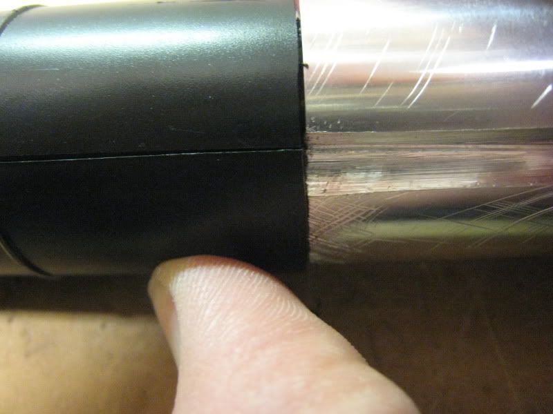
These next four pictures show alignment of the plastic housing with the blade holder. You need to cut two holes into the plastic housing. One for the accent LED and one for the switch leads.
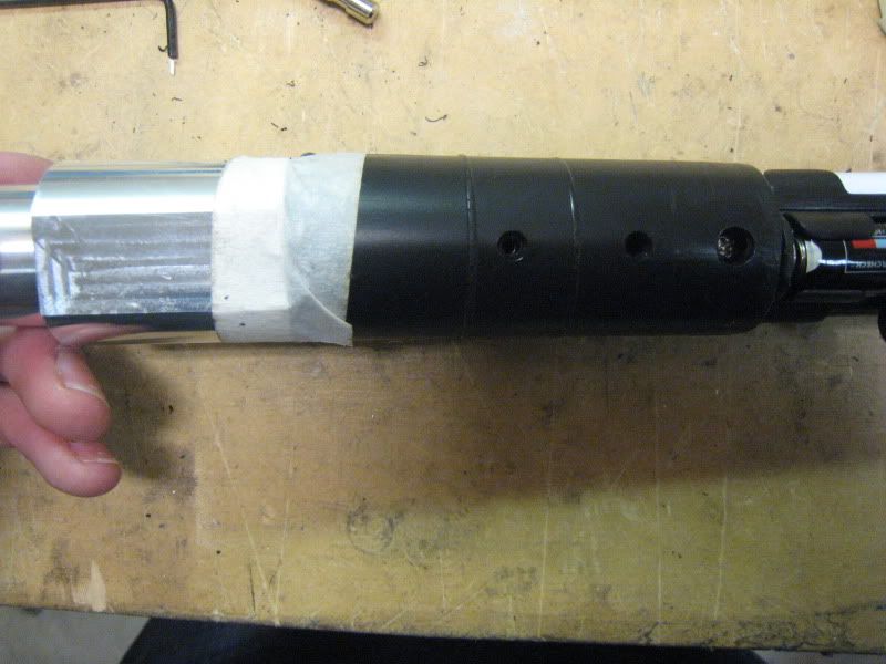
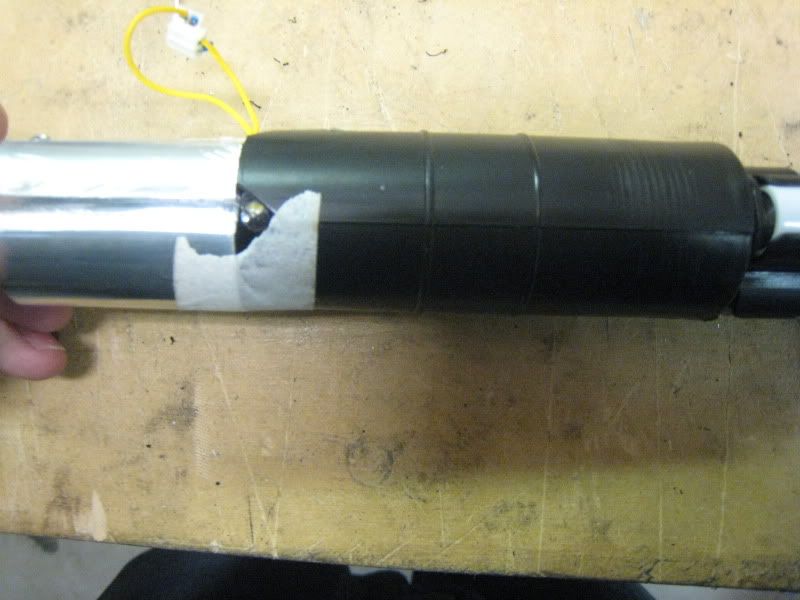
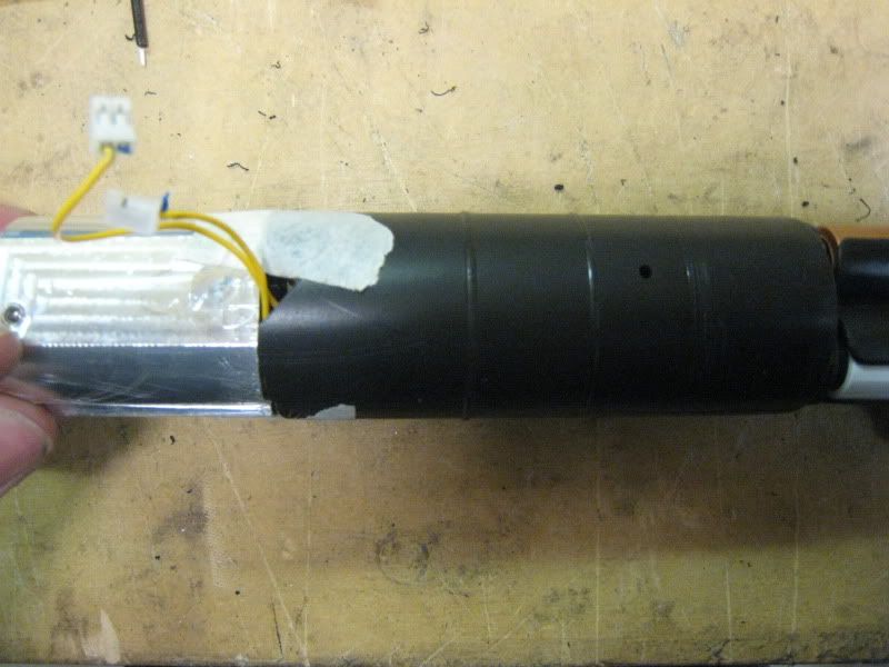
Cut the quick disconnects off your switch leads. Strip and tin the wires. Tape them down to the blade holder.
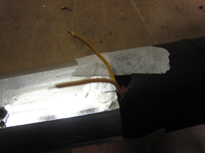
Push the electronics back into the hilt. Pull out the switch leads. Solder on the switch.
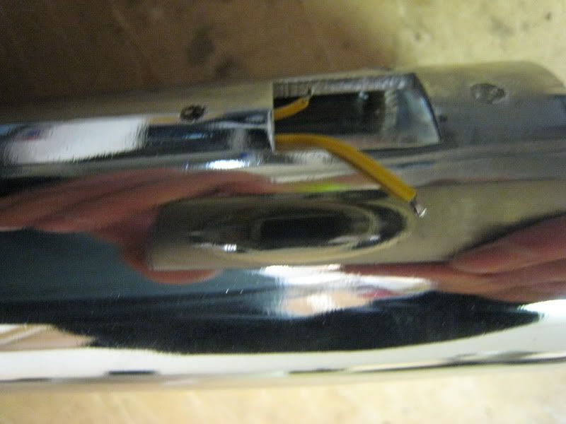
Reassemble the saber in reverse order, except for the two screws pictured.
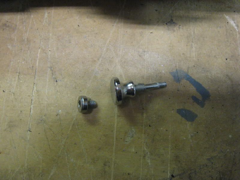
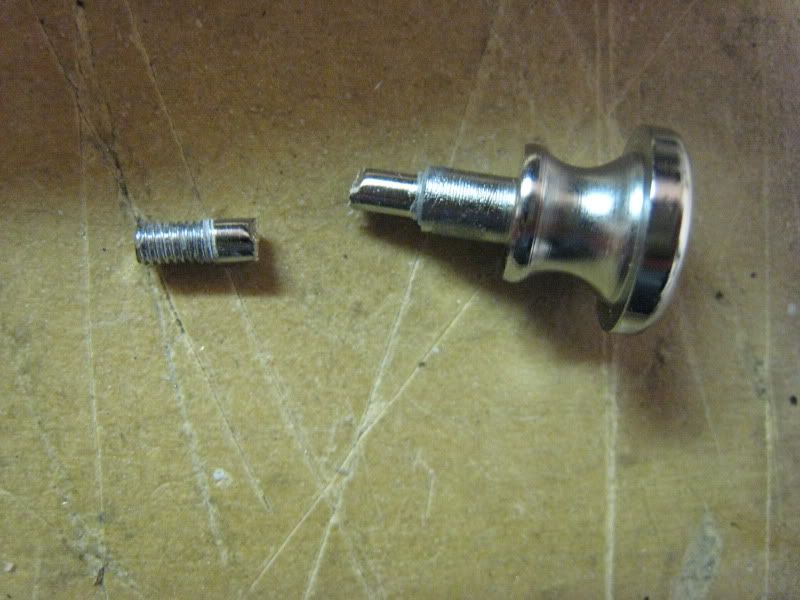
The big thumbscrew is too long to fit with the new blade holder. Cut it down and superglue it in. Be careful not to superglue the whole switch setup together.
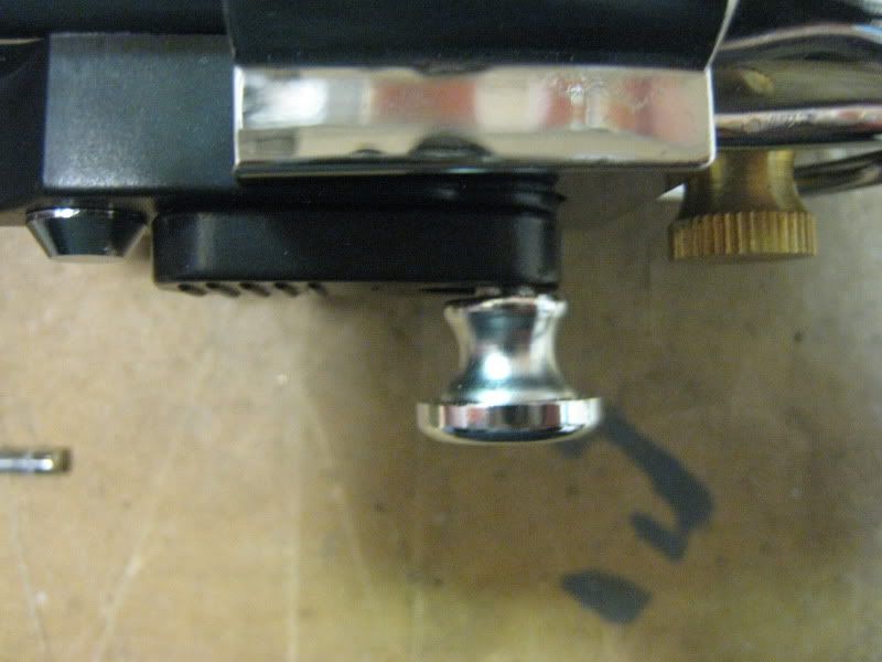
The flat screw will be replaced with a 10-32 thread, 3/8" long screw.
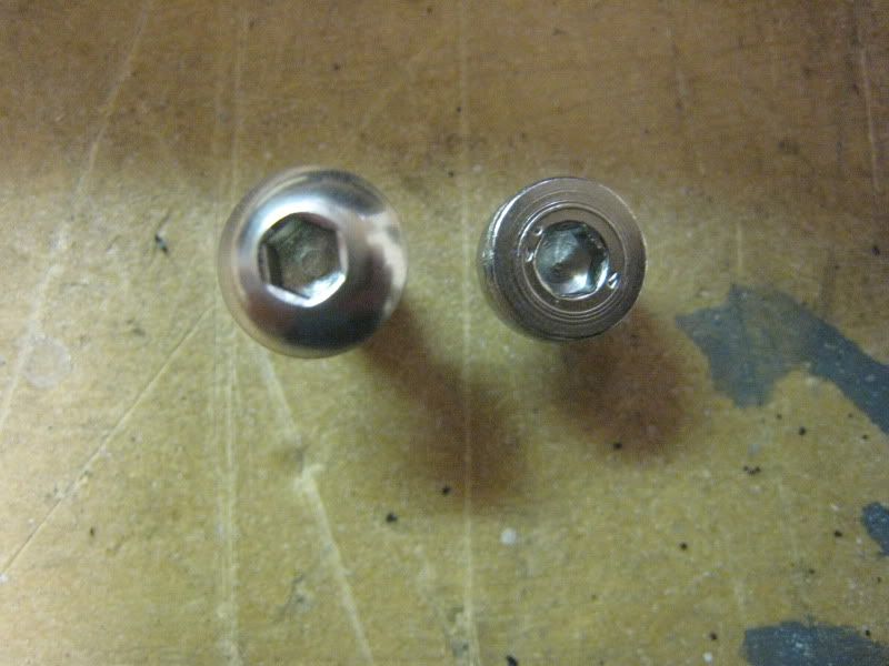
Drill and tap for the new screw, and install it. It won't need any sanding, 3/8" is the perfect length.
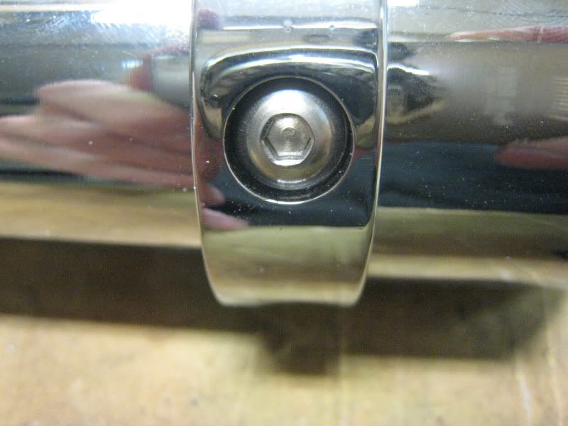
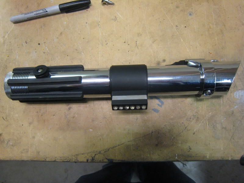
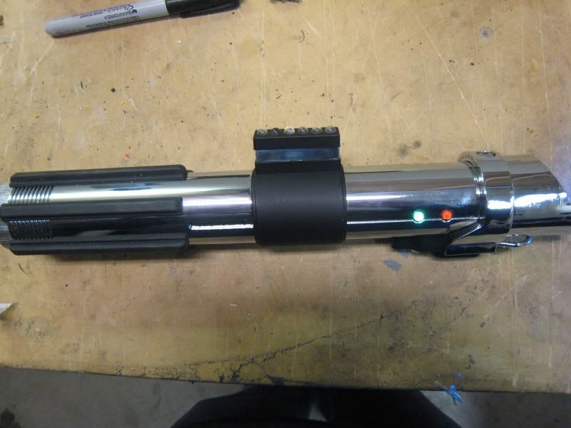
Congratulations, you've converted your saber!
Soldering Wires to a PCB/soundboard
This tutorial will show you the basics of soldering a wire to any kind of PCB. For our purposes, it's usually a sound board.
* First, gather your materials. You'll need a pair of wire strippers, diagonal cutters, solder, and a solder iron

Strip your wire. Only strip 1/8" off or so, no more than the length of the solder pad.
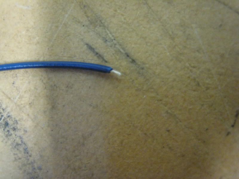
Tin the wire.

Tin the solder pad on the sound board. Don't keep the iron on the pad for too long, this should only take a few seconds. Apply heat to the pad and put the solder on, just like tinning a wire.

Time to solder the wire to the board. Add no more solder, just put the iron on it. Again, this should only take a few seconds.
IMPORTANT NOTE: Don't put the wire through the hole in the sound board. Lay it across the top of the solder pad.


Video: http://www.youtube.com/watch?v=n1Q2gcR81R0
Done!
submitted by: Aluke123
How to solder wires together
In regards to soldering irons.. Any iron will work really. I use a temperature controlled model from Tenma. My backup is a radioshack iron which works fine, too. If you plan on building a lot of sabers, get a nicer iron that heats up fast.

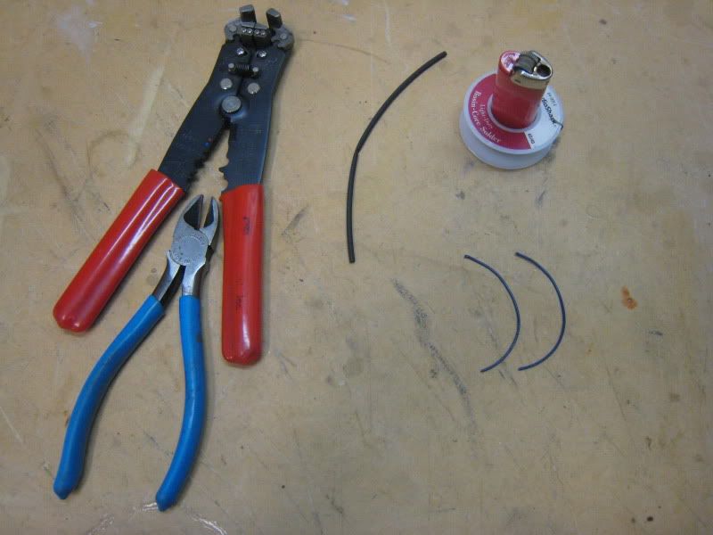
First, gather your materials. Wire strippers, diagonal cutters, heatshrink, solder, lighter (or heat gun), and soldering iron.
Strip both your leads. Take about 1/4" of the insulation off.

Tin the wires. Touch the iron to the wire along with the solder. It should only take a few seconds of contact for the solder to melt and flow over the wire. You should tin BOTH wires.
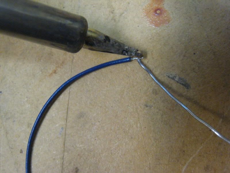
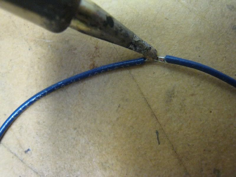
Now it's time to solder the leads together. Slide heatshrink on before you solder, unless one end remains free when you're done. To solder the wires, just touch them together with your iron. Don't add any more solder, the tinning added all you'll need.
IMPORTANT: Tug test the wires when you're done soldering, to be sure that it's a firm joint.

Now slide the heatshrink over the wires. Cut about 1/2" of it.

Shrink the heatshrink tubing down with a lighter. Heat with the blue of the flame so that you don't burn the tubing.

Video: http://www.youtube.com/watch?v=LKvGbEqQTEg
Done!
